AN155 - 利用微控制器调节MP2759 充电电流

每月为您发送最具参考价值的行业文章
我们会保障您的隐私
摘要
很多电池供电设备都需要在不同的工作模式下实时调整充电电流,以提高性能。例如,电池制造商可能要求在不同温度下提供特定的充电电流水平,以保证电池安全。尽管MP2759本身已支持根据JEITA 标准来调节充电电流,但如果采用微控制器 (MCU) ,则可以进一步增强用户配置功能。
MP2759可以通过连接在ISET引脚和AGND之间的电阻 (RISET) 来调节充电电流。本文将介绍一种方法,基于充电电流调节功能,利用MCU来实现MP2759 充电电流的实时调节。文章将介绍MP2759 这款器件,阐述 RISET 与充电电流之间的关系,给出充电电流实时调节MCU方法设计指南,并提供设计示例和测试结果。
简介
MP2759是一款高度集成的开关充电器IC,专为 1 节至 6 节串联锂离子或锂聚合物电池组应用而设计。它支持多种具有不同电池调节电压的电池化学成分,并可以通过 ISET 引脚和 AGND 之间连接的电阻(RISET)来调节充电电流。RISET 与充电电流之间的关系可以用公式(1) 来表达:
$$ I_{\text{CHG}} = \frac{96\,(\text{k}\Omega)}{R_{\text{ISET}}\,(\text{k}\Omega)} $$尽管通过 RISET可以调节充电电流,但其实时调节功能并不可靠。利用MCU 的PWM ,则可以实现更加可靠的充电电流实时调节功能。图 1 所示为MP2759的标准应用原理图。
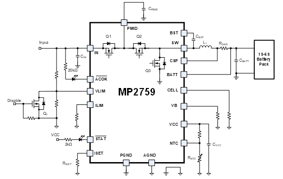
图1: MP2759标准应用原理图
MCU 方法细节
MP2759可以通过ISET引脚读取不同的电阻值来调节充电电流。由于ISET引脚始终保持1.2V的恒定电压,因此改变ISET引脚和AGND之间的等效电阻就可以调节充电电流。通过修改 MCU 的PWM占空比可以带来这种改变。

图2:ISET引脚上的等效电路
MCU 方法概述
图 3 展示了如何设计MP2759 ISET引脚上连接的等效电阻电路。
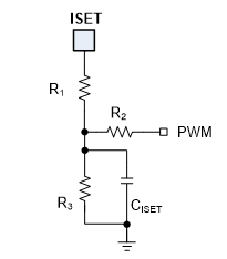
图3: 等效电阻设计电路
PWM信号具有可控占空比。该信号由 MCU 产生,并经过RC 滤波器(由 R2, R3, and CISET组成)滤波为直流信号。ISET引脚和AGND之间的等效电阻 (REQ) 可利用公式 (2) 来计算:
$$ R_{\text{EQ}} = \frac{1.2 R_1 G_{123}}{1.2 G_{123} - \left( \frac{\text{DUTY} \cdot V_{M\_PWM}}{R_2} + \frac{1.2}{R_1} \right)} $$其中DUTY 为PWM占空比,VM_PWM 其中DUTY 为PWM占空比,G123 可通过公式(3)来估算:
$$ G_{123} = \frac{1}{R_1} + \frac{1}{R_2} + \frac{1}{R_3} $$对于公式1、2和3,REQ 必须大于0Ω 。因为当 REQ 降至 0Ω 以下时,ICHG = 0A。表1列出了基于PWM输入得到的充电电流。
表1:充电电流vs. PWM输入
| PWM 输入 | PWM 占空比 | 充电电流 |
| GND | 0% | 最大充电电流 |
| 逻辑高 | 100% | 0A |
| PWM 占空比 | 0% 至 MAX_DUTY(1) | 线性调节充电电流 |
| 浮空 | N/A | 96(kΩ)/R1+R3 |
注:
1) MAX_DUTY是充电电流降至0A时的最大PWM占空比,建议值:约80%。
相关参数设计指南
根据上述分析,可按照以下原则来设计参数 R1, R2, R3, CISET):
其中 fPWM 是PWM频率。
设计示例
本节内容将给出设计示例,当 MAX_ICHG =2.7A,MAX_DUTY =80%,VM_PWM=3.3V,fPWM=2kHz时,如何设计相关参数实现充电电流的实时调节。
设计流程
1. 使用公式(8)计算 RMAX_ICHG :
$$ R_{\text{MAX_ICHG}} = \frac{96\,\text{k}\Omega}{\text{MAX_ICHG}} = 35\,\text{k}\Omega $$2. 选择 R1=20kΩ.
3. 使用公式(6)计算出 R2=33kΩ、R3=27kΩ。
4. 设置 CISET=1µF ,将PWM信号滤波为直流信号。
设计结果
根据上面确定的参数搭建演示板,以验证上述MCU方法的有效性。图4所示为演示板原理图。
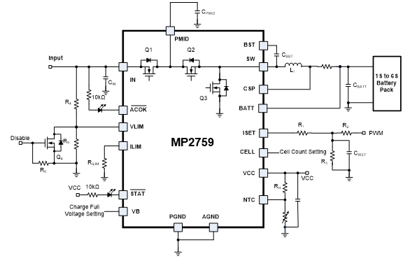
图4: MP2759充电电流调节应用演示板原理图
测试条件: VIN=16V, VBATT=12V, VM_PWM=3.3V, and fPWM=2kHz。对演示板进行测试的结果显示,充电电流和PWM占空比之间存在线性关系,并且占空比具有0%至82%的宽范围(见图5)。
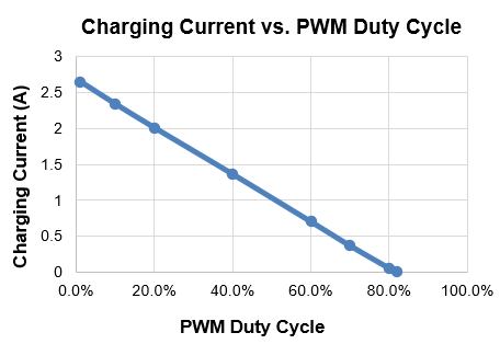
图 5:充电电流vs. PWM占空比
MP2759不会出现过冲或下冲情况(见图 6),器件的启动和关断过程也正常(见图 7)。
所有测试结果均验证了本应用说明中介绍的设计方法有效。
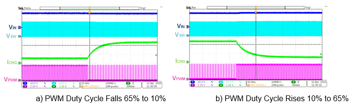
图6: 充电电流在0.5A 和2.4A之间变换
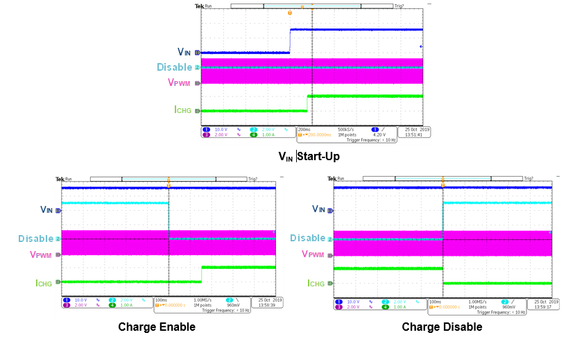
图7: MP2759启动/关断波形(占空比 = 50%)
结语
可调充电电流可以优化充电性能。本应用说明提出了一种利用 MCU 实时调节MP2759充电电流的方法,同时给出了设计示例,并通过测试结果验证了该方法的有效性。
补充资料
有关 MPS 电池管理产品的更多信息,请访问 此页面。
_______________________
您感兴趣吗? 点击订阅,我们将每月为您发送最具价值的资讯!
技术论坛
 Latest activity 11 months ago
 2 回复
Latest activity 6 years ago
2 回复
Latest activity 3 years ago
1 评论
2 回复
Latest activity 6 years ago
2 回复
Latest activity 3 years ago
1 评论
直接登录
创建新帐号