IOUT
mEZDPD3603AS
Session textval
Session Titefor popup
Generating Custom Datasheet
Waveforms of Your Custom Specs
- Start Up
- Steady State
- Load Transient
- Vin Shutdown
- SCP
- Line Transient
- Bode Plot
- Efficiency
- BOM
| 第一步: | 输入定制规格参数并查看定制规格书 |
|
|||||||||||||||||||||||||||||||
|---|---|---|---|---|---|---|---|---|---|---|---|---|---|---|---|---|---|---|---|---|---|---|---|---|---|---|---|---|---|---|---|---|---|
| 第二步: | 保存设计至您的账户 | ||||||||||||||||||||||||||||||||
| 第三步: | 购买您定制的评估板或模块,7天即可交货 | ||||||||||||||||||||||||||||||||
Vo pk-pk: mV @ △Io= A with slew rate 1.6V/us
Target Efficiency: %
Load Current= Efficiency= Power Loss=
Time= Vsw= Vin= Vo= IL= PG= Io=
| Result: | Bandwidth: kHz | Phase Margin: degree |
|
Select a Performance Characteristic to See Results.
| Vin: | V | |
| Io: | A |
| Vin: | V | |
| Io: | A |
| Vin: | V | |
| Io: | A |
| Low Current: | A | |
| High Current: | A | |
| Vin: | V | |
| Vin: | V |
| Low Voltage: | V | |
| High Voltage: | V | |
| Io: | A | |
Notes: For detailed circuit, including the BOM of mEZDPD3603AS, please see the datasheet. Powered by module MPM3596 which includes IC# DIY8886.
Virtual Bench Summary mEZDPD3603AS

 html2canvas
Forced CCM
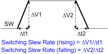
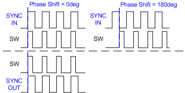
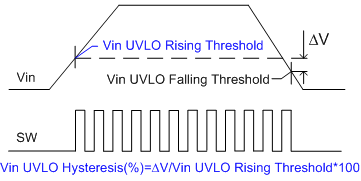
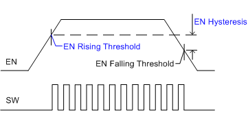
EN Threshold
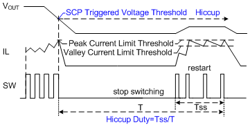
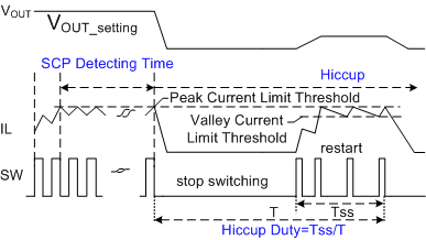
Latch
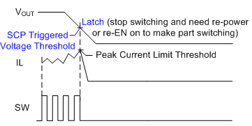
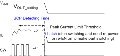
Switching and Non-hiccup
Stop Switching
Latch

Custom Design
Note: Save design to assign PN
Design Name
PRELIMINARY SPECIFICATIONS SUBJECT TO DESIGN FINALIZATION
DESCRIPTION
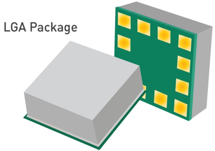
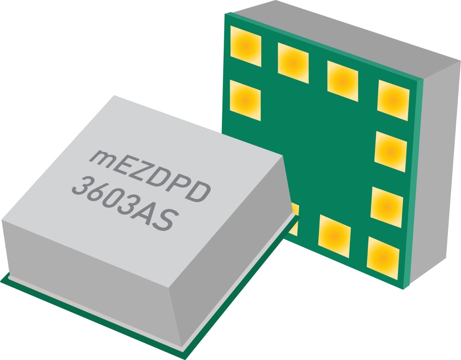
This device is a fully integrated power module that offers ultra-low EMI, in an LGA (15mmx15mmx6mm) metal can. This device meets EN55022 Class-B emissions standards, and integrates internal high- side and low-side power MOSFETs along with an integrated inductor. This device offers a compact solution with minimal external components needed.
SPECIFICATION OVERVIEW
VOUT
Typical VIN
VIN Min
VIN Max
FEATURES
- Power Good and Enable
- Over Temperature Protection (OTP), Short-Circuit Protection
- High Efficiency
- Available in a LGA (15mmx15mmx6mm) Package
EFFICIENCY
VIN = , VOUT = , IOUT =
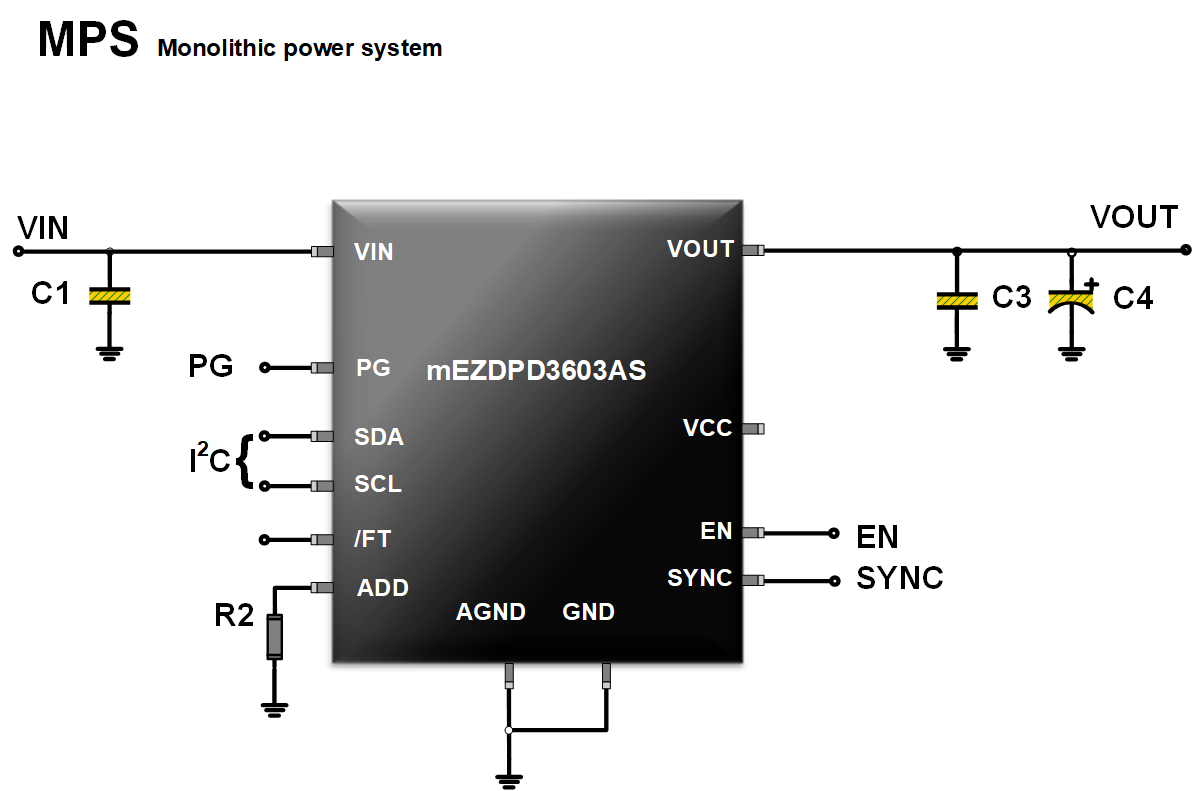
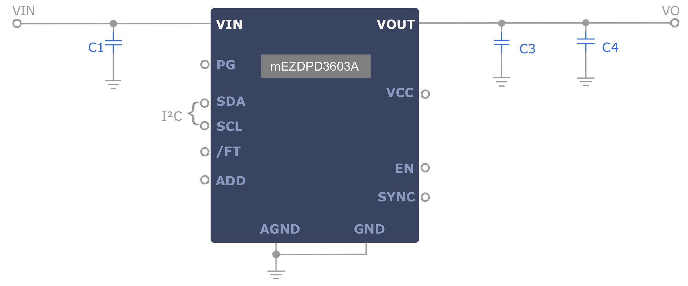
TYPICAL APPLICATION
BOM
Reference
Quantity
Value
Description
Package
Manufacturer
Part Number
C1
NS
C3
C4
U1
1
-
Programmable 36V DC/DC Power module supply up to 3A
'LGA (15x15x6mm)'
MPS
mEZDPD3603AS
ORDERING INFORMATION
Part Number
Finalize Design to Order
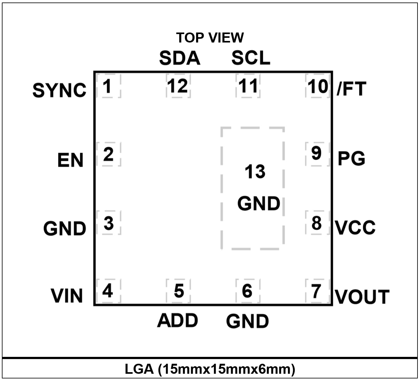
PACKAGE REFERENCE
OTHER ORDERING OPTIONS
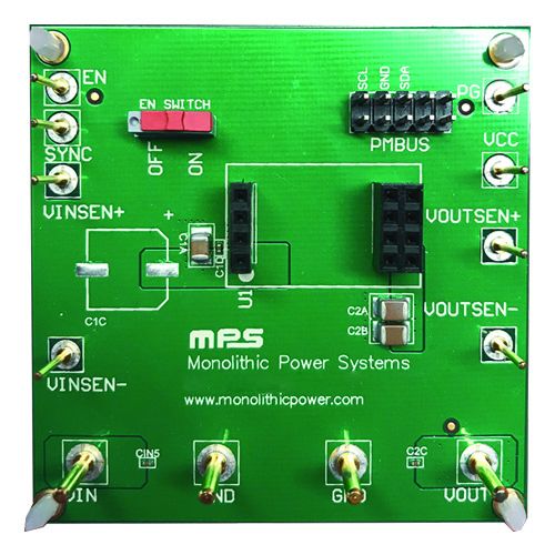
Evaluation Board for Surface Mount Device
The evaluation board is designed to demonstrate the capabilities of your custom MPS Custom PN.
The EVB device is programmed with custom configuration.
Part Number
EVmEZDPD3603AS-00A
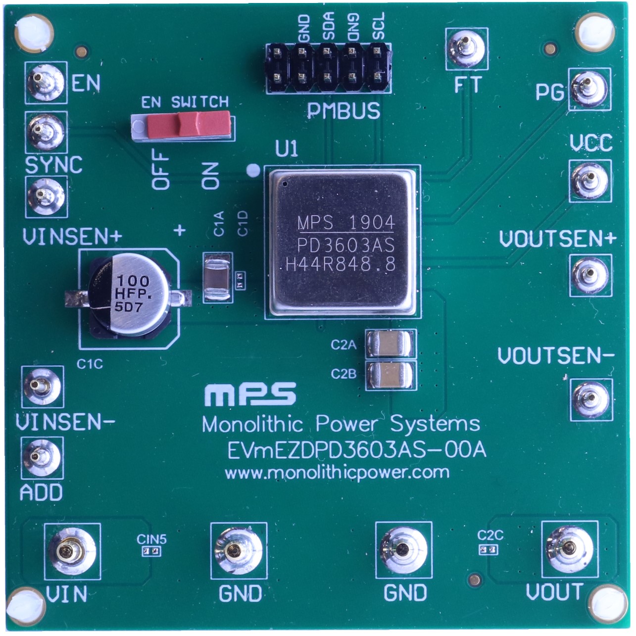
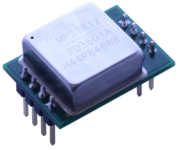
DIP Mount (Pin Out Version)
The Custom PN is your custom device on a DIP mount for an easy-to-use, plug-and-play form factor.
The pin out module device is programmed with custom configuration.
Part Number
mEZDPD3603A
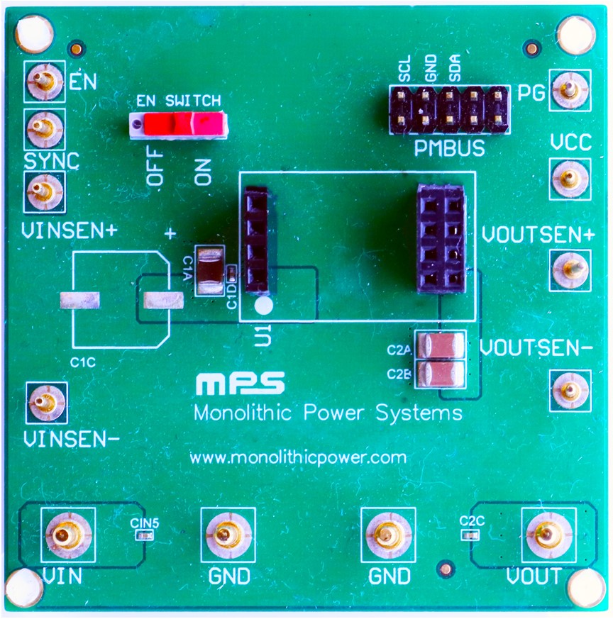
Socket Evaluation Board for DIP Mount
DIP mount socket only. For easy evaluation of pin out module.
Part Number
EVmEZDPD3603A-00A
All EVB schematic and layout files can be found at:
https://www.monolithicpower.com/mezdpd3603as.html
PIN FUNCTIONS
Pin #
Name
Description
1
SYNC
Synchronize. Input, clock synchronization.
2
EN
Enable. Input, drive EN high to turn on the device.
3
GND
Power ground. Power ground.
4
VIN
Input voltage. Input, supply voltage.
5
ADD
Address setting. Address setting for I2C.
6
GND
Power ground. Power ground.
7
VOUT
Output voltage. Sense input of output voltage.
8
VCC
Internal LDO output. Output, internal 5V LDO regulator output.
9
PG
Power good. Output, power good indicator.
10
/FT
Fault indicator. Output, fault indicator.
11
SCL
I2C serial clock. Communication bus, I2C serial clock.
12
SDA
I2C serial data. Communication bus, I2C serial data.
ABSOLUTE MAXIMUM RATINGS
(1)VIN
-0.3V to +48V
VSW
-0.3V to VIN+0.3V
VEN
-0.3V to +48V
All other pins
-0.3V to +5.5V
Continuous power dissipation (TA = 25°C) (2)
TBD W
Junction temperature
150°C
Lead temperature
260°C
Storage temperature
-65°C to +150°C
Operation junction temp (TJ)
-40°C to +125°C
Thermal Resistance (3)
θJA
θJC
LGA (15mmx15mmx4mm)
TBD °C/W
TBD °C/W
- 1) Exceeding these ratings may damage the device.
- 2) The maximum allowable power dissipation is a function of the maximum junction temperature TJ (MAX), the junction-to-ambient thermal resistance θJA, and the ambient temperature TA. The maximum allowable continuous power dissipation at any ambient temperature is calculated by PD (MAX) = (TJ (MAX) - TA) / θJA. Exceeding the maximum allowable power dissipation will cause excessive die temperature, and the regulator will go into thermal shutdown. Internal thermal shutdown circuitry protects the device from permanent damage.
- 3) Measured on JESD51-7, 4 layer PCB.
PROGRAMMABLE ELECTRICAL CHARACTERISTICS
Parameter
Symbol
Condition
Min
Typ
Max
Units
AAM peak current threshold
Programmed value
mA
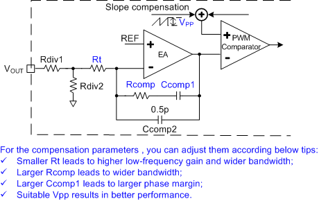
Compensation, RCOMP
RCOMP
Programmed value
kΩ
Compensation, RT
RT
Programmed value, VINUVVTH RISE - VINUVVTH FALL
kΩ
Compensation, CCOMP1
CCOMP1
Programmed value
pF
Slope compensation
Vpp
Programmed value
V
VOUT set
VOUT
Programmed value
V
Switching frequency
FSW
Programmed value
kHz
Switching slew rate (rising) (5)
Programmed value
V/ns
Switching slew rate (failing) (5)
Programmed value
V/ns
Frequency dithering cycle
Programmed value
μs
Frequency dithering amplitude
Programmed value, as proportion of fSW
VIN UVLO rising threshold
INUVVth
Programmed value
V
VIN UVLO hysteresis
INUVHYS
Programmed value
mV
EN rising threshold
VEN
Programmed value
V
EN rising hysteresis
VEN_HYS
Programmed value
mV
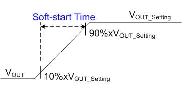
Soft-start time
tss
Programmed value
ms
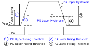
PG upper rising threshold
Programmed value, as % of VOUT set
%
PG upper hysteresis
Programmed value, as % of VOUT set
%
PG lower rising threshold
Programmed value, as % of VOUT set
%
PG lower hysteresis
Programmed value, as % of VOUT set
%
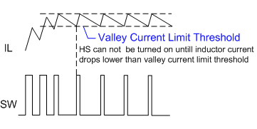
Valley current limit threshold
IVALLEY_LIMIT
Programmed value
A
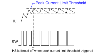
Peak current limit threshold
IPEAK_LIMIT
Programmed value
A
SCP triggered FB voltage
Programmed value, as % of VOUT set
A
SCP detecting time
Programmed value, as % of tsw set
Hiccup duty (on time)
Programmed value
%
Output OVP rising threshold
VOUT_OVP_TH
Programmed value, as % of VOUT set
%
Output OVP hysteresis
VOUT_OVP_HYS
Programmed value, as % of VOUT set
%
Thermal shutdown (5)
TSD
Programmed value. Over-temperature protection threshold
°C
Thermal shutdown hysteresis(5)
TSD_SYS
Programmed value. Over-temperature protection hysteresis
°C
Input OVP rising threshold
VIN_OVP_TH
Programmed value
V
Input OVP hysteresis
VIN_OVP_HYS
Programmed value, as % of input OVP threshold set
%
ELECTRICAL CHARACTERISTICS
VIN = 12V, VEN = 2V, TA= -40°C to +125°C, typical value is tested at TJ = 25°C, unless otherwise noted.
Parameter
Symbol
Condition
Min
Typ
Max
Units
VIN quiescent current
IQ
VOUT = 5V VFB>VREF with BIAS power, no load
600
1000
µA
IQ
VOUT = 5V VFB>VREF with BIAS power, no load (6)
11
μA
VIN shutdown current
ISD
VEN = 0V, TJ =25°C
1
μA
Sync frequency range
fSYNC
Sync clock set range
250
2500
kHz
Sync voltage high threshold
VSYNC_HIGH
1.4
2
V
Sync voltage low threshold
VSYNC_LOW
0.4
1.1
V
Minimum on time (5)
tON_MIN
With peak current mode
80
ns
Minimum off time (5)
tOFF_MIN
380
ns
HS switch on resistance
RDSON_H
VBST - VSW = 5V
95
180
mΩ
LS switch on resistance
RDSON_L
50
100
mΩ
Integrated inductor inductance
L1
10
µH
Inductor DC resistance
L1_DCR
61.5
70
mΩ
PG output voltage low
VPG_SINK
ISINK = 1mA
0.1
0.3
V
PG deglitch timer
tPG_DELAY
30
µs
VCC regulator
VCC
ICC = 0mA, with VCC LDO powered by VIN
4.8
5
5.2
V
Input OVP threshold accuracy
I2C set 36V
32
34
36
V
Note:
5) Not tested in production. Guaranteed by design and characterization.
PROGRAM OPERATION SETTINGS
Name
Selected
Description
Note
Light Load Mode
AAM/forced CCM
0
0: AAM
1: Forced CCD
Switching
Frequency dithering Enable
0
0: Disable
1: Enable
Protection
SCP mode
0
0: Hiccup
1: Latch
2: Switching and Non-hiccup
Output OVP mode
1
0: Discharge
1: Stop switching
2: Latch
FT setting
1
Fault flag
0: Latch
1: Auto-reset
I2C SIGNAL CHARACTERISTICS
VIN = 12V, VEN = 2V, TA = -40°C to +125°C, typical values tested at TJ = 25°C, unless otherwise noted.
Parameters
Symbol
Condition
Min
Typ
Max
Units
I2C Interface Specifications
Input logic low
VIL
0
0.4
V
Input logic high
VIH
1.3
V
Output logic low
VOL
ILOAD = 3mA
0.4
V
SCL clock frequency
fSCL
400
kHz
SCL high time
tHIGH
0.6
μs
SCL low time
tLOW
1.3
μs
Data set-up time
tSU,DAT
100
ns
Data hold time
tHD,DAT
0
0.9
μs
Set-up time for repeated start
tSU,STA
0.6
μs
Hold time for start
tHD,STA
0.6
μs
Bus free time between a start and a stop condition
tBUF
1.3
μs
Set-up time for stop condition
tSU,STO
0.6
μs
Rise time of SCL and SDA
tR
20 + 0.1 × CB
120
ns
Fall time of SCL and SDA
tF
20 + 0.1 × CB
120
ns
Pulse width of suppressed spike
tSP
0
50
ns
Capacitance bus for each bus line
CB
400
pF

TYPICAL PERFORMANCE CHARACTERISTICS
All waveforms simulated.
EFFICIENCY
VIN = , VOUT = , IOUT =
LINE TRANSIENT
Vlow = , Vhigh = , Iout = , Slew rate =
START-UP
VIN = , IOUT =
VIN SHUTDOWN
VIN = , IOUT =
STEADY STATE RIPPLE
VIN = , IOUT =
LOAD TRANSIENT
VIN = , IHIGH = , ILOW = , Slew Rate =
SCP
VIN =
BODE PLOT
Bandwith = , Phase Margin = , Gain Margin =
FUNCTIONAL BLOCK DIAGRAM
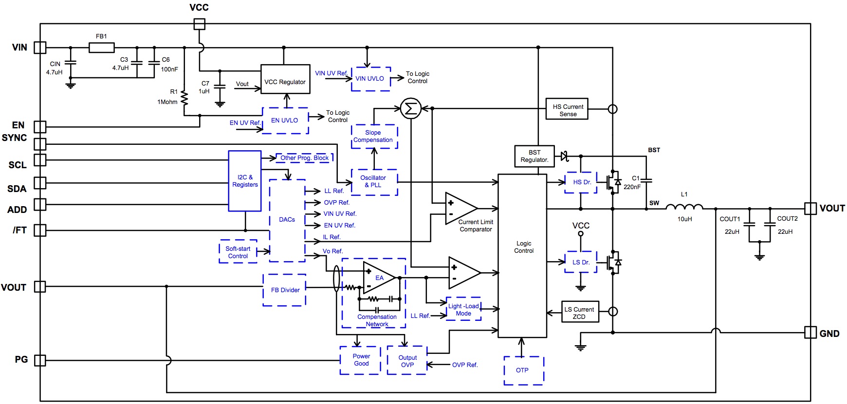
OPERATION
This device is a high-frequency, synchronous, step-down power supply. It is available with a wide 4.5V to 36V input supply range and can achieve up to 3A continuous output current with excellent load and line regulation over an ambient temperature range of -40°C to +125°C.
PWM Control
At moderate to high output currents, this device operates in a fixed-frequency, peak current control mode to regulate the output voltage. An internal clock initiates a PWM cycle. Then the rising edge of the clock the high-side switch (HS-FET) turns on and the inductor current rises linearly to provide energy to the load. The HS-FET remains on until its current reaches the COMP voltage, which is the output of the internal error amplifier. The output voltage of error amplifier depends on the difference of output feedback voltage and the internal high-precision reference. It determines how much energy should be transferred to the load. The higher the load current, the higher the COMP voltage will be. Both the feedback divider ratio and reference can be adjusted by the I2C, which makes it easy to adjust for different output voltages.
When the HS-FET is off, the low-side switch (LS-FET) turns on immediately and remains on until the next clock starts. During this time, the inductor current flows through the LS-FET. In order to avoid shoot-through, dead time is inserted to avoid the HS-FET and LS-FET turning on at the same time.
If in one PWM period, the current in the HS-FET does not reach the COMP set current value, the HS-FET remains on, saving a turn-off operation.
Mode Selection (AAM and Forced CCM)
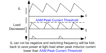
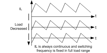
This device can operate in light load AAM or forced CCM mode. AAM (advanced asynchronous modulation) mode is employed to optimize the efficiency during light-load or no-load conditions. Forced CCM can maintain a constant switching frequency and smaller output ripple, but it has low efficiency at light load.
If AAM mode is enabled with load decreasing, the device enters discontinuous conduction operation (DCM) with fixed-frequency as long as the inductor current approaches zero. If the load is further decreased or there is no load that makes the inductor peak current below AAM peak current threshold set by the I2C, the device enters sleep mode. In sleep mode, it consumes very low quiescent current to further improve light-load efficiency. The internal clock is also blocked, and the device skips some pulses. The feedback voltage is less than the reference, so VCOMP ramps up until the inductor peak current exceeds the AAM threshold. Then the internal clock is reset, and the crossover time is taken as the benchmark of the next clock. This control scheme helps achieve high efficiency by scaling down the frequency to reduce switching and gate driver losses.
As the output current increases from light load, VCOMP and the switching frequency increase. If the output current exceeds the critical level set by VCOMP, the device resumes fixed-frequency PWM control.
When forced CCM is enabled, the device operates in fixed-frequency peak current control mode to regulate the output voltage, regardless of the output current.
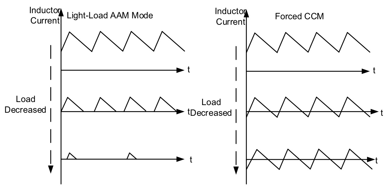
Figure 6: A Complete Data Transfer
Internal Regulator
A 5V internal regulator powers most of the internal circuitries. This regulator takes VIN and operates in the full VIN range. When VIN exceeds 5.0V, the output of the regulator is in full regulation. Lower VIN values result in lower output voltages. The regulator is enabled when VIN exceeds its UVLO threshold and EN is high. In EN shutdown mode, the internal VCC regulator is disabled to reduce power dissipation.
For better thermal performance, BIAS mode can be chosen via the I2C if VOUT is greater than 5V. VCC and the internal circuit are then powered by VOUT.
Enable Control
EN is a digital control pin that turns the regulator, including I2C block on and off. Drive EN high to turn on the regulator; drive it low to turn the regulator off. The EN threshold can be programmed by the I2C. An internal 5MΩ resistor from EN to GND allows EN to be floated to shut down the chip.
Oscillator Frequency
The default frequency of this device is 500kHz, and it can be programmed from 250kHz to 2.5MHz by the I2C. The frequency can also be set by a logic level synchronal signal.
SYNC IN and SYNC OUT
The SYNC pin can be programmed by the I2C to SYNC IN or SYNC OUT. When operating as SYNC IN, the internal oscillator frequency can be synchronized by an external clock via this pin. At start-up, the device first operates at the internal set frequency, and quickly synchronizes to the external clock once soft start is ready. Ensure the high amplitude of the SYNC clock is above 1.8V and the low amplitude is below 0.4V to drive the internal logic. The recommended external SYNC frequency is between 250kHz and 2.5MHz
The device operates in forced CCM mode with a fixed frequency when there is a SYNC clock, regardless of the output current. A pulse longer than 200ns is recommended in application.
When the SYNC pin is set to SYNC OUT, the device can output the internal clock with a 0° or 180° phase shift. By this function, two devices can operate in same frequency but 180° out of phase to reduce the total input current ripple so that a smaller input bypass capacitor can be used.
Under-Voltage Lockout (UVLO)
The device has input under-voltage lockout protection (UVLO) to ensure reliable output power. Assuming EN is active, the device is powered on when the input voltage exceeds the UVLO rising threshold, and is powered off when the input voltage drops below the UVLO falling threshold. The UVLO threshold can be set between 3.3V and 7.5V the I2C. This function prevents the device from operating at an insufficient voltage. It is a non-latch protection.
Soft-Start
The device has built-in soft start (SS), which ramps up the output voltage in a controlled slew rate when the EN pin goes high, avoiding overshoot during start-up. When the chip starts, the internal circuitry generates a soft-start voltage that ramps up slowly. When the SS voltage (VSS) is below the internal reference (VREF), VSS overrides VREF as the error amplifier reference. When VSS exceeds VREF, VREF acts as the reference. At this point, soft start finishes and the device enters steady state.
The SS time is internally set to default 1ms, and can also be set to 0.5ms, 2ms, or 4ms by the I2C. When the output voltage is shorted to GND, the feedback voltage is pulled low and VSS is discharged. The part soft starts again when it returns to its normal state.
Pre-Bias Start-Up
For this device, at start-up, if the output feedback voltage is greater than VSS, which means the output has pre-bias voltage, neither the HS-FET nor LS-FET turn on until VSS exceeds the feedback voltage.
Power Good Indicator
This device has power good (PG) indication. The PG pin is the open drain of a MOSFET. It should be connected to a voltage source through a resistor (e.g. 100kΩ). In the presence of an input voltage, the MOSFET turns on so that the PG pin is pulled to GND before soft start is ready. When the output voltage is within default ±10% window of the rated voltage, the PG pin is pulled high after a delay (typically 30μs).
If VOUT moves outside the default ±10% range with a hysteresis, the device pulls PG low to indicate a failure output status. Both the PG threshold and hysteresis can be programmed by the I2C.
FAULT Indicator
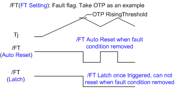
The /FT pin is also an open drain of a MOSFET. It should be connected to a voltage source through a resistor (e.g. 100kΩ). The /FT pin is pulled high in normal operation, and any fault or warning pulls this pin low to indicate a fault status, including input OVP, output OVP, SCP, and thermal shutdown.
Over-Current Protection (OCP)
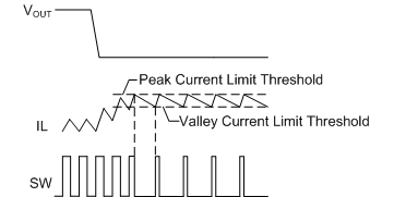
This device has cycle-by-cycle over-current limit control. The inductor current is monitored during the HS-FET on state. Once the inductor peak current exceeds the set current limit threshold, the HS-FET immediately turns off. Then the LS-FET turns on to discharge the energy, and the inductor current decreases. The HS-FET does not turn on again until the inductor current is below a certain current threshold, called the valley current limit. This prevents the inductor current from running away and possibly damaging the components. Both the peak current and valley current threshold can be programmed by the I2C.
When the peak current limit is triggered, the OCP timer starts immediately. The OCP timer can be set to 32, 64, 128, or 256 cycles by the I2C. Reaching the current limit during each cycle during this OCP timer triggers SCP operation (hiccup as default), which is introduced in the following section.
Short-Circuit Protection (SCP)
When a short circuit occurs, this device immediately reaches its current limit. Meanwhile, the output voltage quickly drops to its under-voltage threshold¬ (default is 50% of the setting output). The device considers this an output dead short and directly triggers SCP operation. Three modes can be selected by the I2C for SCP operation: hiccup as default, switching with non-hiccup, and latch-off.
In default hiccup mode, this device disables its output power stage and resets the soft-start voltage, then initiates a soft start. The off time is determined by the soft-start time and hiccup duty, which can both be set by the I2C. If the short-circuit condition still remains after soft start ends, the device repeats this operation until the short circuit disappears and the output returns to the regulation level. This protection mode greatly reduces the average short-circuit current by periodically restarting the part to alleviate thermal issues and protect the regulator.
Output Over-Voltage Protection (VOUT OVP)
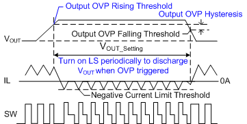
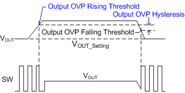
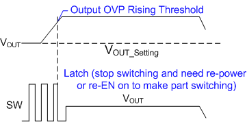
This device monitors the output voltage through the VOUT pin to detect output over-voltage conditions. When the output voltage exceeds OVP threshold (the default is 120% of the setting voltage), OVP mode is triggered. Three modes can be selected by the I2C for OVP operation: disable as default, discharge, and latch-off.
Input Over-Voltage Protection (VIN OVP)
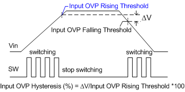
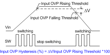
This device also has optional input OVP. The threshold can be set to 28V, 34V, or 40V. If VIN exceeds the threshold, the device stops switching. This is a non-latch protection, and there is a hysteresis of either 2.5% or 5% of the input OVP threshold voltage. The device resumes normal operation when the input OVP is removed. Both the input OVP threshold and hysteresis can be set by the I2C interface.
Thermal Shutdown
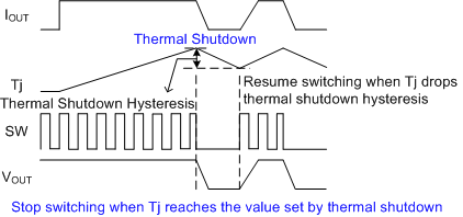
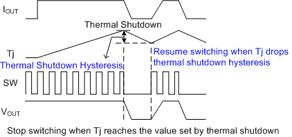
This device has over-temperature protection (OTP) by monitoring the IC temperature internally. This function prevents the chip from operating at exceedingly high temperatures. If the junction temperature exceeds the threshold (default 175°C), it shuts down the whole chip. This is a non-latch protection, and there is a default 25°C hysteresis. Once the junction temperature drops to about 150°C, the device resumes operation by initiating a soft start. Both the OTP threshold and hysteresis can be set by the I2C interface.
Floating Driver and Bootstrap Charging
An external bootstrap capacitor powers the floating power MOSFET driver. The floating driver has its own UVLO protection, with a rising threshold of 2.5V and hysteresis of 200mV.
The bootstrap capacitor voltage is charged to about 5V from VCC through a PMOS pass transistor when the LS-FET is on.
In high duty cycle operation or sleep mode, the bootstrap charging time period is shorter, so the bootstrap capacitor may not be charged sufficiently. In case the external circuit does not have sufficient voltage and time to charge the bootstrap capacitor, extra external circuitry can be used to ensure the bootstrap voltage is in the normal operation range.
Low-Dropout Operation (BST Refresh)
To improve dropout, the device is designed to operate at close to 100% duty cycle as long as the BST to SW pin voltage is greater than 2.5V. When the voltage from BST to SW drops below 2.5V, the high-side MOSFET turns off using a UVLO circuit that allows the low-side MOSFET to conduct and refresh the charge on the BST capacitor.
In cases where the input voltage drops, the HS-FET remains on and close to 100% duty cycle to maintain output regulation, until the BST to SW voltage falls below 2.5V. Since the supply current sourced from the BST capacitor is low, the high-side MOSFET can remain on for more switching cycles than are required to refresh the capacitor. Therefore, the effective duty cycle of the switching regulator is high.
The effective duty cycle during dropout of the regulator is mainly influenced by the voltage drops across the power MOSFET, inductor resistance, low-side diode, and PCB resistance.
I2C Control and Default Output Voltage
When the device is enabled (which means EN = high and VIN > UVLO), the chip starts up to a default 5V output voltage. After that, the I2C bus can communicate with master. Once the I2C receives a valid output voltage set instruction, the output voltage is determined by the I2C control.
The output voltage is set by adjusting the internal reference voltage and output feedback divider ratio. After this device receives a valid data byte of output voltage setting, it searches the corresponding value from the truth table and then sends the command of adjusting reference and divider ratio. Finally, it outputs the correct voltage.
Frequency Dithering for Low EMI
Frequency dithering is a technique used in the power industry to reduce EMI, especially for EMI-sensitive applications. This spread-spectrum modulation technique spreads the frequency spectrum of converter, which in turn spreads the energy of the switching harmonics over a wider band while reducing their amplitudes, helping to meet stringent EMI goals
The programmable frequency dithering feature of this device allows either 3/48 or 3/28 variation range in the switching frequency, with a 120µs or 150µs dithering cycle. Both the frequency dithering range and cycle can be set by the I2C interface.
Multi-Page One-Time-Programmable Memory
The device features three pages of one-time-programmable memory to store desired settings permanently.
Differential one-time-programmable cells, rather than single-ended, are used for long-term reliability. Data is stored on two floating gate avalanche injection metal oxide semiconductor (FAMOS), and output comparators are used for differential reading.
The first page of the multi-page one-time-programmable memory has been programmed with manufacturer default values.
Once the device is enabled, the default values on the first page are used to set the control parameters in the registers. If there is data on other pages of the one-time-programmable memory, the newest setting is identified by an internal indicator to write registers. See the Register Map and Register Description sections for details.
I2C INTERFACE
I2C Serial Interface Description
I2C is a two-wire, bidirectional serial interface, consisting of a data line (SDA) and a clock line (SCL). The lines are externally pulled to a bus voltage when they are idle. Connecting to the line, a master device generates the SCL signal and device address, then arranges the communication sequence. The device’s interface is an I2C slave, which supports both fast mode (400kHz) and typically high-speed mode (3.4MHz), adding flexibility to the power supply solution. The output voltage, transition slew rate, or other interesting parameters can be instantaneously controlled by the I2C interface.
Data Validity
One clock pulse is generated for each data bit transferred. The data on the SDA line must be stable during the high period of the clock. The high or low state of the data line can only change when the clock signal on the SCL line is low (see Figure 4).
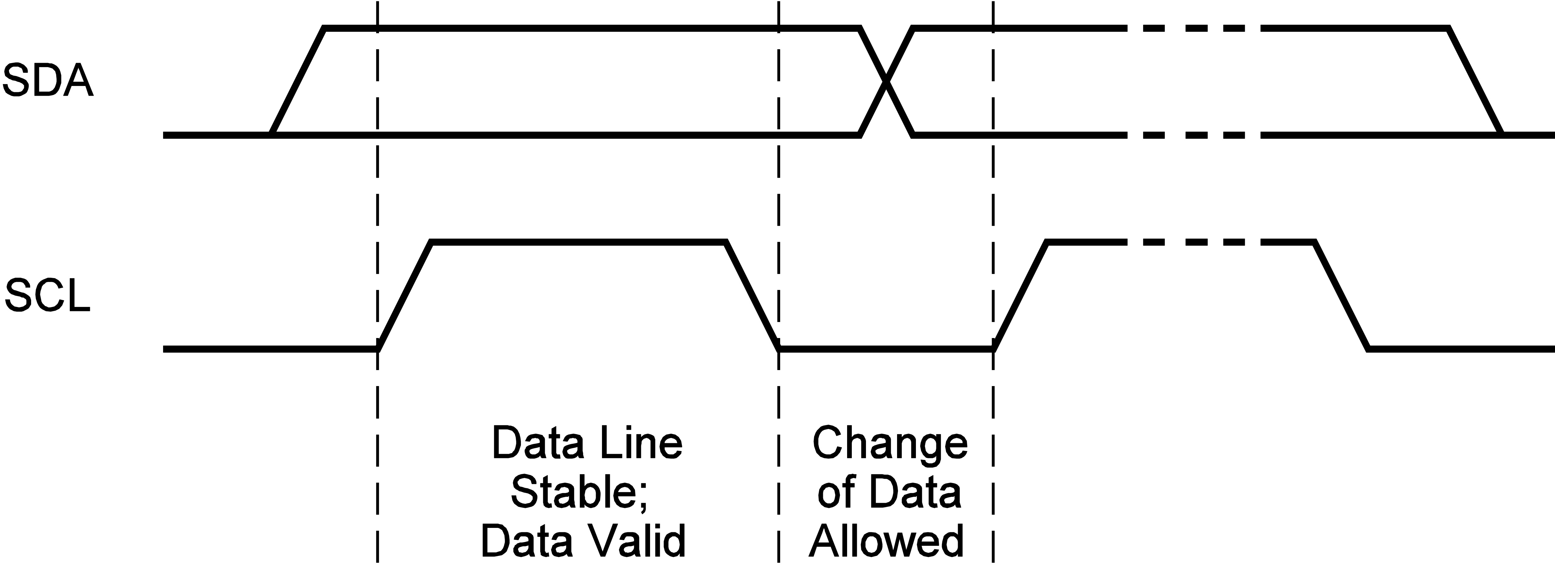
Figure 4: Bit Transfer on the I2C Bus
Start and Stop Conditions
Start and stop conditions are signaled by the master device, which signifies the beginning and the end of the I2C transfer. A start condition (S) is defined as the SDA signal transitioning from high to low while the SCL is high. A stop condition (P) is defined as the SDA signal transitioning from low to high while the SCL is high (see Figure 5).

Figure 5: Start and Stop Conditions
Start and stop conditions are always generated by the master. The bus is considered busy after the start condition. The bus is considered free again after a minimum of 4.7μs after the stop condition.
The bus stays busy if a repeated start (Sr) is generated instead of a stop condition. The start and repeated start conditions are functionally identical.
Transfer Data
Every byte put on the SDA line must be 8 bits long. Each byte must be followed by an acknowledge (ACK) bit. The acknowledge-related clock pulse is generated by the master.
The transmitter releases the SDA line (high) during the acknowledge clock pulse. The receiver must pull down the SDA line during the acknowledge clock pulse, so that it remains stable low during the high period of the clock pulse.
Figure 6 shows the format that data transfers follow. After the start condition, a slave address is sent. This address is 7 bits long, followed by an 8th data direction bit (R/W). A 0 indicates a transmission (write), and a 1 indicates a request for data (read). A data transfer is always terminated by a stop condition, generated by the master. However, if a master still wishes to communicate on the bus, it can generate a repeated start condition and address another slave without first generating a stop condition.
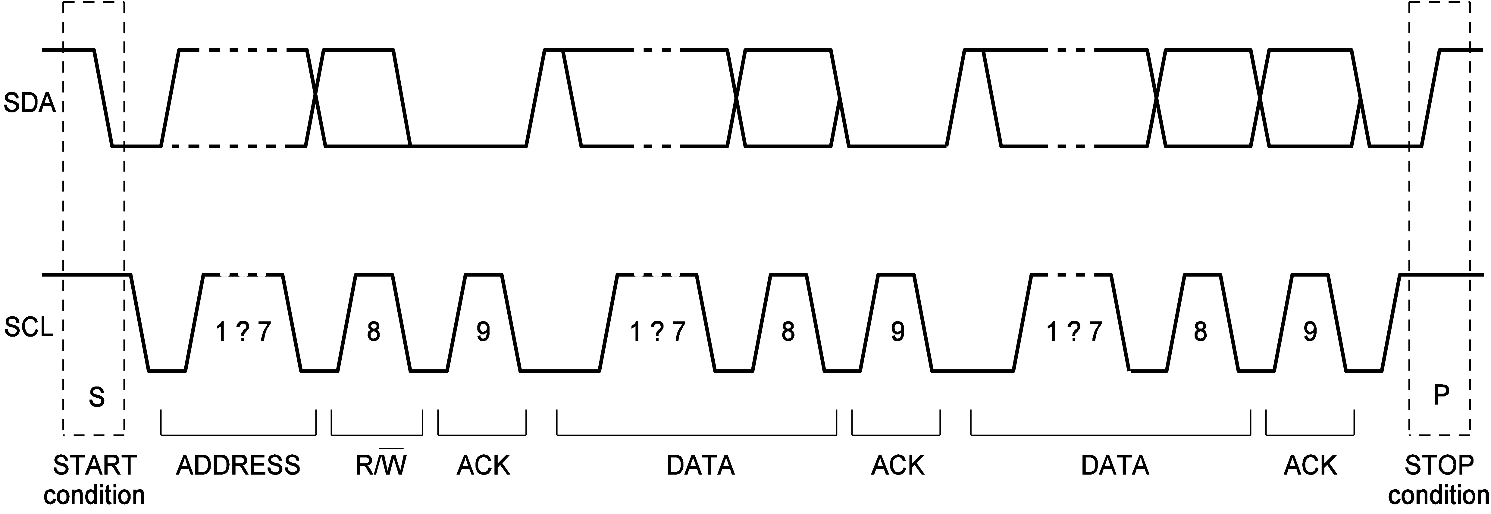
Figure 6: A Complete Data Transfer
I2C Chip Address
The ADD pin can be used to program the I2C address. This device supports eight addresses for up to eight voltage rails through configuring the resistor value that connects the ADD pin and ground. When the master sends the address as an 8-bit value, the 7-bit address should be followed by “0/1” to indicate write/read operation.
I2C Update Sequence
This device requires a start condition, a valid I2C address, a register address byte, and a data byte for a single data update. After receipt of each byte, the device acknowledges by pulling the SDA line low during the high period of a single clock pulse. A valid I2C address selects the device. The device performs an update on the falling edge of the LSB byte.
Table 1 shows the resistor values for different I2C addresses.
Table 1: I2C Address| Resistor (kΩ) 1% | Addresses |
|---|---|
| 0 to 21.5 | 21h |
| 22 to 47 | 22h |
| 47.5 to 71.5 | 23h |
| 73.5 to 97.3 | 24h |
| 100 to 124 | 25h |
| 127 to 147 | 26h |
| 150 to 174 | 27h |
| >178 | 28h |
PACKAGE INFORMATION
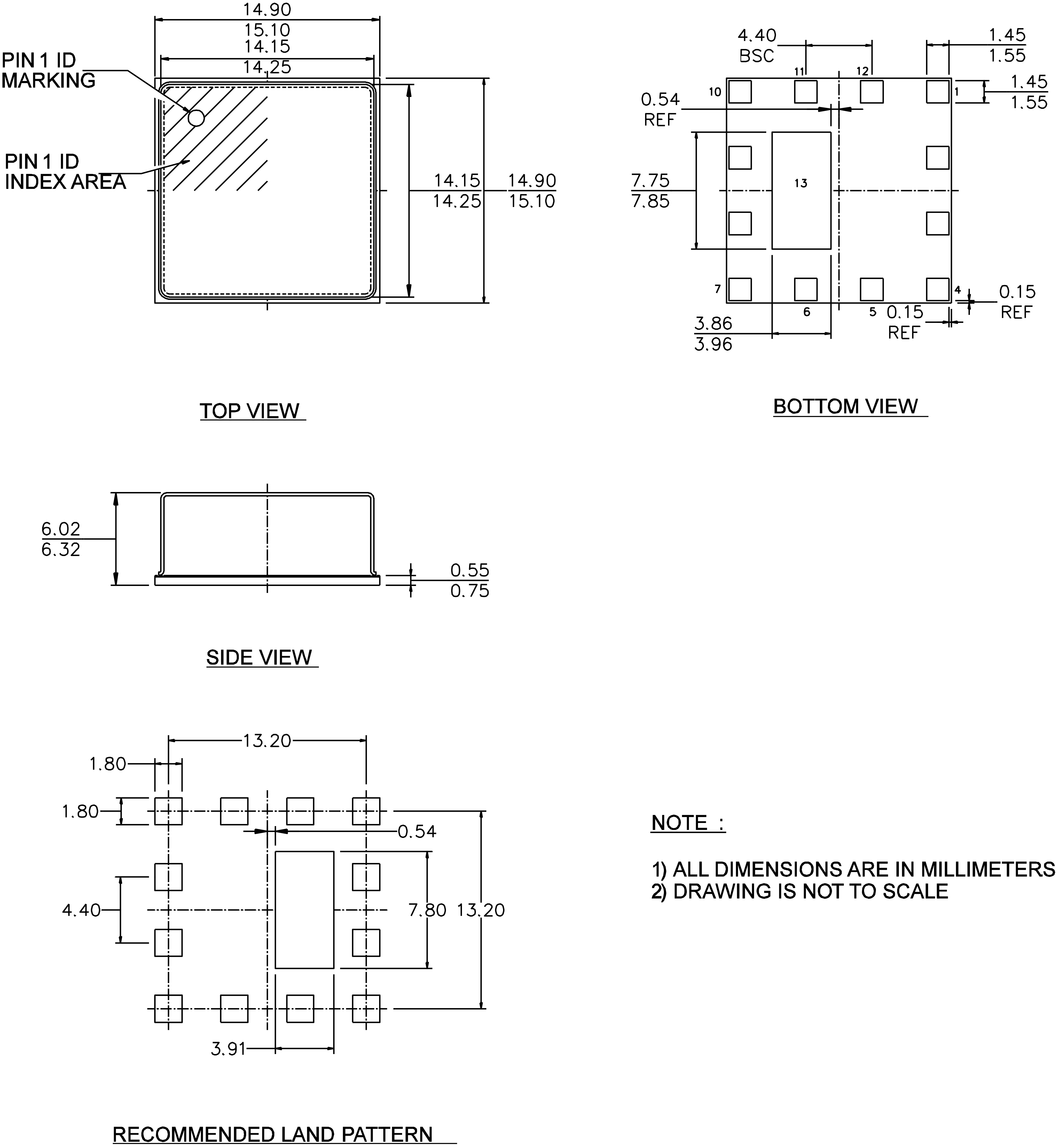
LGA (15mmx15mmx6mm)
NOTICE: The information in this document is subject to change without notice. Please contact MPS for current specifications. Users should warrant and guarantee that third-party Intellectual Property rights are not infringed upon when integrating MPS products into any application. MPS will not assume any legal responsibility for any said applications.
mEZDPD3603AS是一款可配置的 DC/DC 降压电源模块,输出电流最高可达 3A,输出电压范围为0.6-12V.该模块具有可多次编程的存储器,可使用简单的GUI进行编程。

mEZDPD3603AS具有数字可编程功能,可通过I2C PMBus 控制和编程,可编程的工作参数包括:补偿值、输出电压转换速率、开关频率和省电模式。预先配置的DIP封装模块可以提供快速评估。
想要自定义配置预加载到评估板模块吗?您可以在此创建并保存模块配置,然后下单购买评估板。
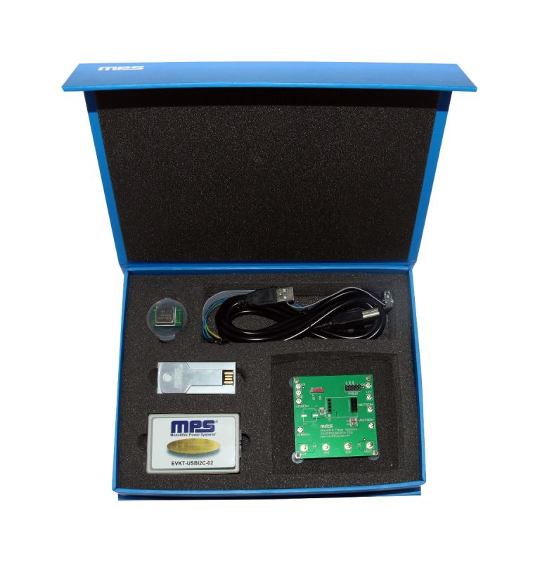
PKT-mEZDPD3603A 是 mEZDPD3603A 可编程电源模块的一款编程工具。
PKT-mEZDPD3603A 是 mEZDPD3603A 可编程电源模块的一款编程工具。 mEZDPD3603A 是一款可编程的 DC/DC 电源模块,输出电流最高可达3A,输出电压可达 0.6V-12V。该模块具有可多次编程的存储器,可使用 GUI 或虚拟平台 Pro 2.2 进行编程,亦可在此下载。
GUI 包含了一个可用于验证芯片性能的建模软件。在实验评估期间,通过I2C接口可轻松获得不同的配置。这使得用户可以根据他们的需求优化每个输出。所有未编程的部件(mEZDPD3603A-XXXX )也仅需要设置输出电流值和输出电压值即可开始评估。GUI 中定义的具有默认设置的其他参数,用户也可根据需要进行修改。/p>
¥677.35 + 税
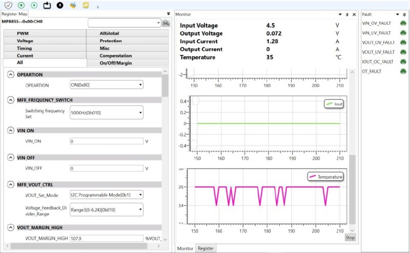
配置和检测 I2C 数字接口&评估板的软件
| 查看&编辑寄存器 检测器
|
硬件&软件要求:
|
| 使用具有评估套件的软件和采用 I2C 通信协议的产品 | |
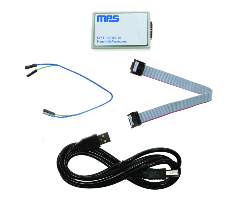
USB 转 I2C/PMBus 通信接口设备,包含在产品评估套件中,也可单独购买
EVKT-USBI2C-02 包含在产品评估套件中,也可单独购买。该通信接口同时兼容USB 转 I2C 端口和 USB 转 PMBus 端口。它是设计用于 MPS I2C 和 PMBus 产品和虚拟平台及 I2C GUI 工具上。与 MPS 虚拟平台和 I2C GUI一起使用可以简单快速地评估 MPS 的数字产品性能。
EVKT-USBI2C-02 套件包括:
- 1 个 USB 转 I2C 通信设备接口
- 1 根 USB 线
- 1 根 10 芯排线
- 1 根 3 芯排线
- 带有规格书和驱动文件的拇指驱动
¥356.50 + 税


 了解更多我们的评估板套件


直接登录
创建新帐号