AN193 - Selecting the MP2760’s BATFET

Get valuable resources straight to your inbox - sent out once per month
We value your privacy
Abstract
Portable devices today increasingly require a longer usage time, shorter charging time, and limited system voltage (VSYS). A shorter charging time requires a higher charging current (ICHG) within the heat loss tolerance. To achieve a limited VSYS and accurate ICHG, many manufacturers use a narrow-voltage DC (NVDC) architecture for battery-charging applications.
The MP2760 is an I2C-controlled, 1-cell to 4-cell buck-boost charger with NVDC power path management. A battery FET (BATFET) driver is included to control an external N-channel MOSFET, which regulates the system’s minimum voltage (VSYS_REG_MIN) and provides a battery supplement function. Different BATFET characteristics may affect ICHG.
This application note discusses the features of the MP2760, as well as the relationship between ICHG and the BATFET’s characteristics. It also provides a design example for selecting the BATFET.
Introduction
The MP2760 provides a BATFET driver (via the BGATE pin) to support NVDC power path management. The device can regulate the system voltage at VSYS_REG_MIN, even when the battery is depleted.
Figure 1 shows the NVDC power path management structure.
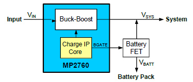
Figure 1: NVDC Power Path Management Structure
The MP2760 has a configurable VSYS_MIN. When VBATT < VSYS_REG_MIN (where VSYS_REG_MIN = VSYS_MIN + VTRACK), the BATFET driver controls the charging current loop (trickle charge, pre-charge, and linear constant-current (CC) charge). This ensures that VSYS is regulated at VSYS_REG_MIN.
When VBATT > VSYS_REG_MIN, the BATFET fully turns on, and the charging current loop (switching CC charge) and battery voltage loop (constant voltage (CV) charge) are implemented via the buck-boost converter’s pulse-width modulation (PWM) control. VSYS always tracks the actual battery voltage, which is limited above VBATT by VTRACK.
Figure 2 shows the system voltage regulation, where RSYS_BAT is the total resistance between the system and battery.
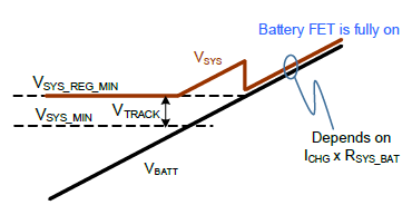
Figure 2: System Voltage Regulation
Figure 3 show the MP2760’s charging profile.

Figure 3: Complete Charging Cycle Profile
Method Details
Linear Charging Current
When VBATT is below VSYS_REG_MIN, BATFET works linearly. In 1-cell applications, the charge pump is powered by VCC, which is the internal LDO output that can provide a 3.6V voltage for the internal circuit. The charge pump’s input determines the maximum charge pump output (VCP). VCP is then used to drive the external BATFET via a current source.
The current source’s output impedance (ZISRC) should be several hundred kΩ, and the charge pump’s output impedance (ZO_CP) should be between several kΩ and several tens of kΩ. If the selected BATFET’s gate-to-source threshold voltage (VGS_TH) results in an insufficient DC voltage bias (about 2V) for the current source, then ZISRC drops to several tens of kΩ, and ICHG drops below its configured value (ICHG_CONF) due to inadequate loop gain. Therefore, a proper BATFET must be selected to meet the required minimum charging current (ICHG_REQ), especially for 1-cell applications.
Figure 4 shows the simplified block diagram of the BATFET’s linear on loop in a 1-cell application.
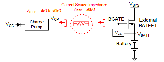
Figure 4: Simplified Block Diagram of the BATFET’s Linear On Loop in 1-Cell Applications
Figure 5 shows the relationship between the MP2760’s ICHG and the BATFET’s gate-to-source voltage (VGS) when ICHG_CONF is set to 1A, which reflects the driving ability under 1-cell applications. In 2-cell to 4-cell applications, the charge pump’s input is sufficiently high, and the current source that drives BATFET does not become saturated. Due to this, this application note only provides guidance on selecting BATFET in 1-cell applications.
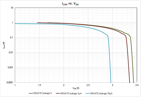
Figure 5: ICHG vs. VGS of the MP2760’s BATFET (ICHG_CONF = 1A)
Figure 6 shows the transfer characteristics of three different N-channel MOSFETs. These characteristic curves are paired with the curves from Figure 5 on page 4.
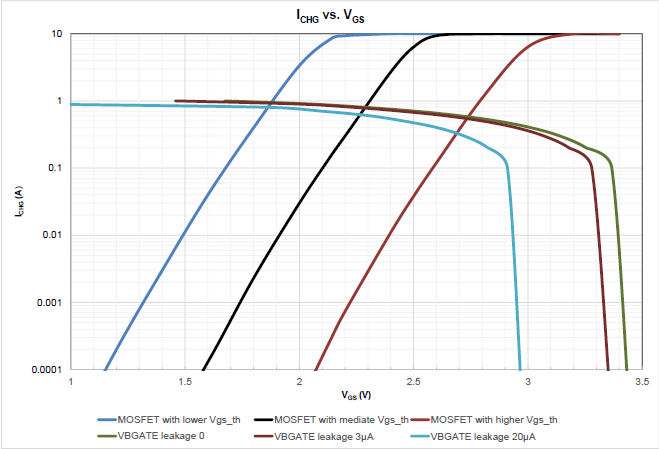
Figure 6: Estimated ICHG When the MP2750's BATFET Works Linearly with Different MOFSET Types (ICHG_CONF = 1A)
Based on Figure 6, it is possible to estimate the BGATE pin voltage (VBGATE) and ICHG values for different MOSFET types. Table 1 lists the estimated VGS and ICHG values to select a MOSFET with the optimal transfer characteristics.
Table 1: Estimated VGS and ICHG Values(1) (2) (3)
| VBGATE Leakage (μA) | VTH Low Sample | VTH Typical Sample | VTH High Sample | |||
|---|---|---|---|---|---|---|
| VGS (V) | ICHG (A) | VGS (V) | ICHG (A) | VGS (V) | ICHG (A) | |
| 0 | 1.86 | 0.95 | 2.29 | 0.8 | 2.74 | 0.55 |
| 3 | 1.86 | 0.95 | 2.29 | 0.8 | 2.73 | 0.52 |
| 20 | 1.85 | 0.85 | 2.26 | 0.6 | 2.69 | 0.32 |
Notes:
- These estimated valuesresult from a 1A ICHG_CONF. When ICHG_CONF increases by 500mA, the actual ICHG also increases by about 500mA.
- This application note only discusses 1-cell applications.
- If there is any external leakage current (ILKG) pulled from BGATE, such as the BATFET’s gate-to-source discharge resistance (RGS), the results are different.
If the selected MOSFET is not sufficient to make ICHG reach ICHG_REQ, there are two methods to ensure ICHG reaches ICHG_REG, described below:
- Increase the BATFET’s drain-to-source voltage (VDS) by increasing VTRACK to shift its transfer characteristics curve left. This results in a higher ICHG. Note that VTRACK cannot be set too high because a higher VDS causes additional losses on the BATFET.
- Set ICHG_CONF higher to meet the minimum ICHG requirement.
Switching Charging Current
When VBATT exceeds VSYS_REG_MIN, the BATFET fully turnson,and its linear on loop does not impact ICHG. Instead, ICHG is limited by VTRACK, as calculated with Equation (1):
$$ I_{\text{CHG}} = \frac{V_{\text{TRACK}}}{R_{\text{SNS}} + R_{\text{DS(ON)}} + R_{\text{PCB}}} $$Where RSNS is the ICHG sense resistance, RDS(ON) is the on resistance of the BATFET when it is fully on, and RPCB is the parasitic resistance of the PCB.
Based on Equation (1), RDS(ON) must satisfy the constraints estimated with Equation (2):
$$ R_{\text{DS(ON)}} < \frac{V_{\text{TRACK}}}{I_{\text{CHG_REQ}}} - R_{\text{SNS}} - R_{\text{PCB}} $$If the BATFET RDS(ON) is not low enough, VTRACK can be set higher via the I2C to ensure that ICHG_REQ is met.
Design Example
This section demonstrates how to successfully select a proper BATFET in a 1-cell application to meet the ICHG requirement for both linear charge mode and switching charge mode.
Consider the following design parameters as an example. ICHG_REQ is set to 0.8A in linear charge mode and 4A in switching charge mode. Based on the following conditions, in linear charge mode, ICHG_CONF is 1A, the minimum drain-to-source voltage (VDS_MIN) is 100mV, and RGS is 1MΩ. In switching charge mode, ICHG_CONF is 4A, VTRACK is 100mV, and RSNS is 10mΩ.
Figure 7 shows the MP2760’s typical application circuit.
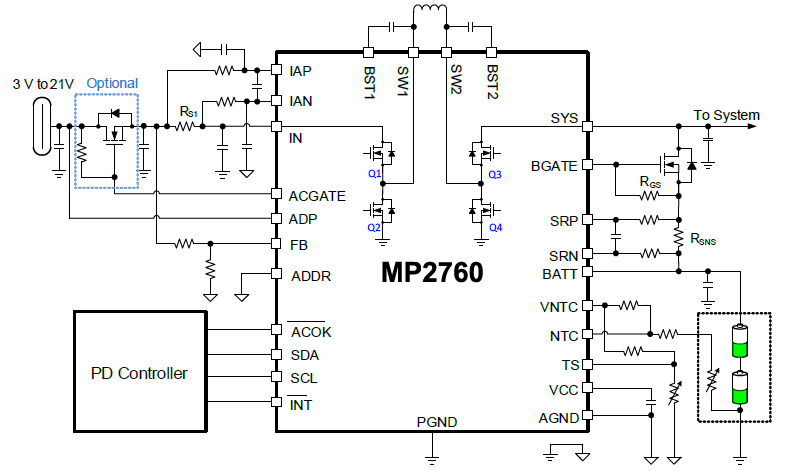
Figure 7: Typical Application Circuit of the MP2760
Linear Charge Mode
To meet the ICHG requirement for linear charge mode, follow the steps below:
- Based on Figure 6 on page 5, when ICHG_REQ is set to 0.8A, VGS is between 2V and 2.5V.
- The leakage current (ILKG) pulled from the external BGATE can be calculated with Equation (3): $$ I_{\text{LKG}} = \frac{V_{\text{GS}}}{R_{\text{GS}}} = \frac{2\,\text{V to }\,2.5\,\text{V}}{1\,\text{M}\Omega} = 2\,\mu\text{A to }\,2.5\,\mu\text{A} $$
- Based on Table 1 on page 5, when ICHG_REQ is set to 0.8A, VGS is about 2.29V.
- Select an N-channel MOSFET with a proper transfer characteristics curve at VDS = 0.1V,where the drain-to-source current (IDS) exceeds 0.8A when VGS is 2.29V.
Switching Charge Mode
Ignoring the parasitic impedance on the PCB, the BATFET RDS(ON) can be calculated with Equation (4):
$$ R_{\text{DS(ON)}} < \frac{100\,\text{mV}}{4\,\text{A}} - 10\,\text{m}\Omega = 15\,\text{m}\Omega $$Conclusion
The NVDC architecture has been increasingly implemented in battery charger applications. The MP2760 is a battery charger that provides NVDC power path management using an external BATFET. The BATFET selection impacts NVDC performance, especially in 1-cell applications.
This application note proposed a method for selecting a proper BATFET with suitable characteristics, ensuring the ICHG requirements are met in both linear charge mode and switching charge mode.
Additional Reading
For more information about MPS battery management products, contact an MPS FAE or visit the MPS website.
_______________________
Did you find this interesting? Get valuable resources straight to your inbox - sent out once per month!
技术论坛
 Latest activity a year ago
 4 回复
Latest activity 8 months ago
4 回复
Latest activity 2 months ago
7 回复
4 回复
Latest activity 8 months ago
4 回复
Latest activity 2 months ago
7 回复
直接登录
创建新帐号