Principles of Passive Filtering
Passive filters play an integral role in harmonic elimination in power systems. These filters operate on the basic principles of electrical circuit theory, harnessing the characteristic behaviors of resistors, inductors, and capacitors to selectively eliminate unwanted frequencies.
A passive filter is a combination of resistors, capacitors, and inductors arranged in various configurations to achieve a desired filtering effect. The main function of a passive filter is to allow certain frequencies to pass while blocking or attenuating others. This is primarily achieved by exploiting the frequency-dependent impedance characteristics of capacitors and inductors.
Capacitors and inductors exhibit different impedance characteristics with respect to frequency. The impedance (Z) of a capacitor is inversely proportional to the frequency (f) and the capacitance (C), given by Z = 1/(2πfC). As the frequency increases, the impedance decreases, thus capacitors tend to 'block' low-frequency signals and 'pass' high-frequency signals. On the other hand, the impedance of an inductor is directly proportional to the frequency and the inductance (L), given by Z = 2πfL. Inductors tend to 'pass' low-frequency signals and 'block' high-frequency signals.
In the context of power systems, passive filters are typically designed to 'block' or 'trap' harmonic frequencies while allowing the fundamental frequency to pass. This is usually achieved by designing the filter such that its impedance is high at the harmonic frequencies and low at the fundamental frequency.
The effectiveness of a passive filter in eliminating harmonics depends on its design and placement in the power system. The design involves selecting the appropriate resistance, inductance, and capacitance values to achieve the desired filtering effect. The placement of the filter in the power system is also crucial, as it should be located close to the source of the harmonics for effective elimination.
It is important to note that while passive filters are relatively simple and cost-effective, they are less flexible than active filters. Their performance can be influenced by changes in the system's operating conditions. Therefore, careful design and implementation are necessary to ensure their effective operation.
Types of Passive Filters
Passive filters are classified into different types based on frequency response characteristics and circuit configurations. Three commonly used types of passive filters in harmonic elimination are single-tuned filters, double-tuned filters, and high-pass filters.
Single-Tuned Filters
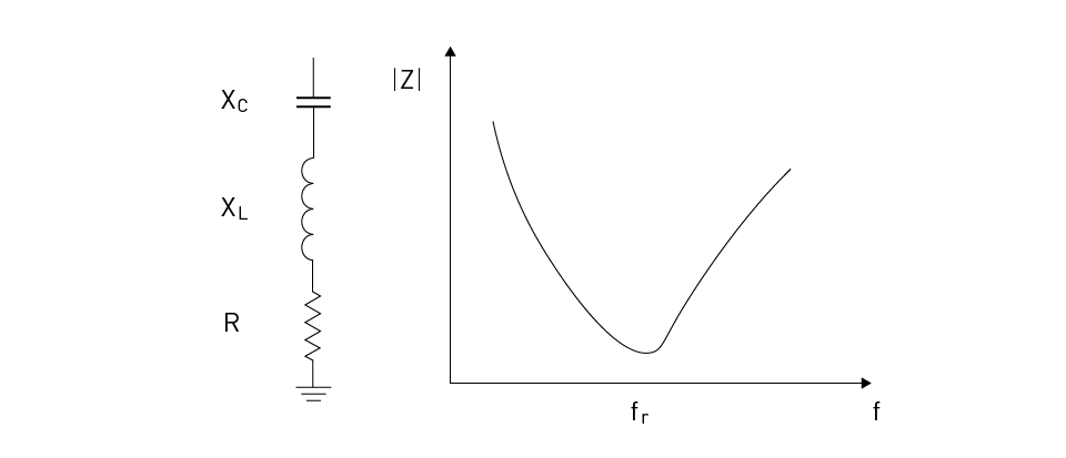
A single-tuned filter, also known as a series filter, allows a specific frequency to pass while attenuating all other frequencies. This type of filter consists of a series resonant circuit with an inductor (L) and a capacitor (C). The circuit's resonant frequency (fr) is determined by the values of L and C, given by fr = 1/(2π√LC). At the resonant frequency, the filter's impedance is at its minimum, allowing the corresponding harmonic to pass. All other frequencies see a higher impedance and are thus attenuated. Single-tuned filters are typically designed to target a specific troublesome harmonic in a power system.
Figure 1 shows the circuit schematic and a typical impedance characteristic for the single-tuned filter.

Figure 1: Single-Tuned Filter
Double-Tuned Filters
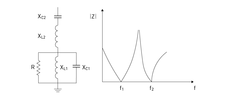
A double-tuned filter is a combination of two single-tuned filters. It is designed to allow two specific frequencies to pass while attenuating all other frequencies. This type of filter is useful when two significant harmonics need to be eliminated. The design of a double-tuned filter involves selecting the inductance and capacitance values for each resonant circuit such that they resonate at the two target harmonic frequencies.
Figure 2 shows the circuit schematic and a typical impedance characteristic for the double-tuned filter.

Figure 2: Double-Tuned Filter
High-Pass Filters
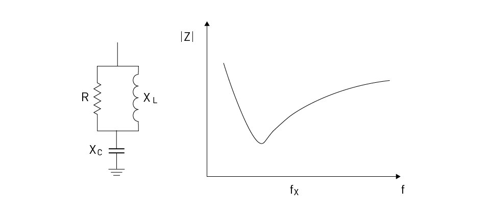
A high-pass filter allows all frequencies above a certain cut-off frequency to pass while attenuating all frequencies below the cut-off. This type of filter consists of a series circuit with a resistor (R) and a capacitor (C). The cut-off frequency (fc) is determined by the values of R and C, given by fc = 1/(2πRC). At frequencies above the cut-off, the filter's impedance decreases, allowing the frequencies to pass. At frequencies below the cut-off, the filter's impedance increases, attenuating the frequencies. High-pass filters are useful in power systems where there are many high-order harmonics that need to be eliminated.
Figure 3 shows the circuit schematic and a typical impedance characteristic for the high-pass filter.

Figure 3: High-Pass Filter
Design Considerations for Passive Filters
Designing a passive filter for harmonic elimination in a power system requires careful consideration of several factors, including filter tuning, filter rating, impedance, and filter placement in the power system.
Filter tuning refers to selecting the values of the inductive and capacitive components of the filter to make it resonate at the harmonic frequency that needs to be eliminated. The tuning process is critical to ensure that the filter provides the minimum impedance at the harmonic frequency, thus effectively eliminating it. For instance, the resonant frequency of a single-tuned filter is given by fr = 1/(2π√LC), where L is the inductance, and C is the capacitance. In the case of a double-tuned filter, two sets of LC circuits are tuned to resonate at two different frequencies.
The filter rating defines the maximum current or voltage a filter can handle without degrading its performance or causing damage. It is determined by the power rating of the inductive and capacitive components used in the filter. The filter impedance at the resonant frequency should be low to allow the harmonic current to pass through the filter and high at the fundamental frequency to prevent it from being shunted through the filter. Accurate calculation of the filter impedance is vital to ensure that the filter functions as intended without causing unwanted power losses.
The placement of the filter in the power system is another critical design consideration. Ideally, the filter should be placed as close as possible to the source of the harmonics. This helps to prevent the harmonic currents from propagating through the power system, reducing the potential for harmonic-related problems such as increased losses, interference with other equipment, and degradation of power quality. Additionally, the filter should be placed where it can effectively mitigate the harmonics without causing power flow issues or compromising the stability of the power system.


直接登录
创建新帐号