Introduction
Modern electronic systems cannot function without three-phase inverters, which transform DC power into three-phase AC power with adjustable amplitude, frequency, and phase difference. They are essential in several applications, including as power distribution networks, renewable energy systems, and industrial motor drives. The primary features and benefits of three-phase inverters over single-phase inverters are highlighted in this section.
We will go through numerous three-phase inverter types, their essential parts, and circuit topologies in the following sections.
Circuit Topology
Commonly the full-bridge topology is used for three-phase inverters.
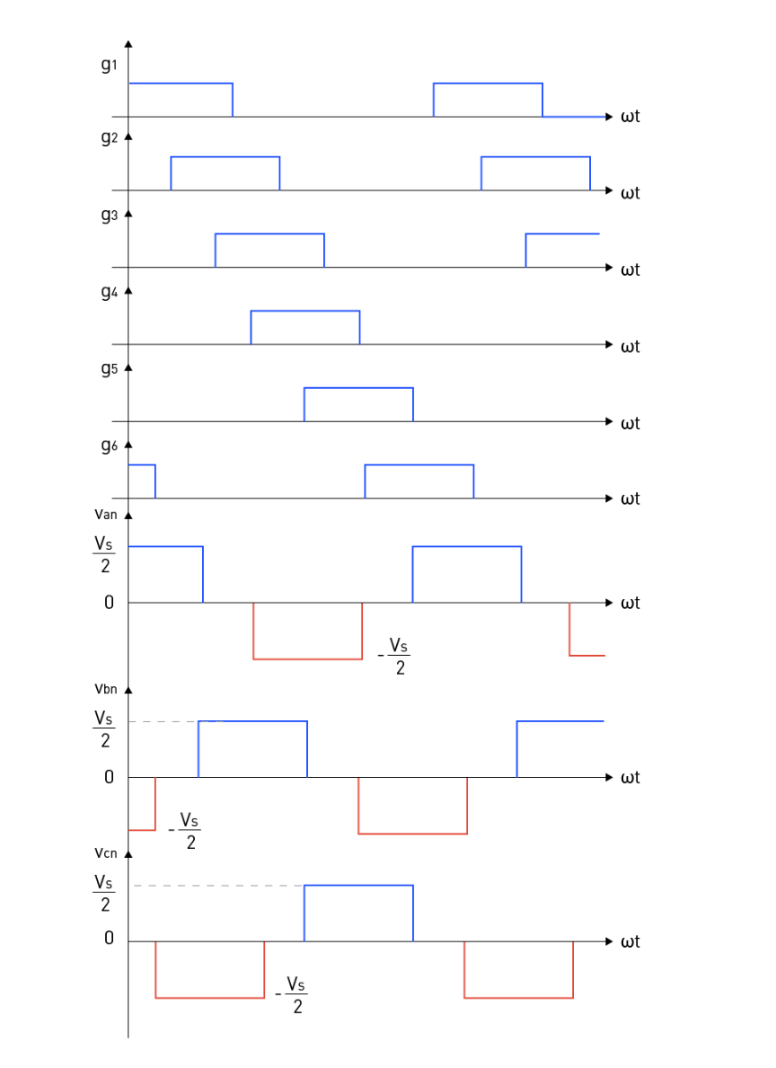
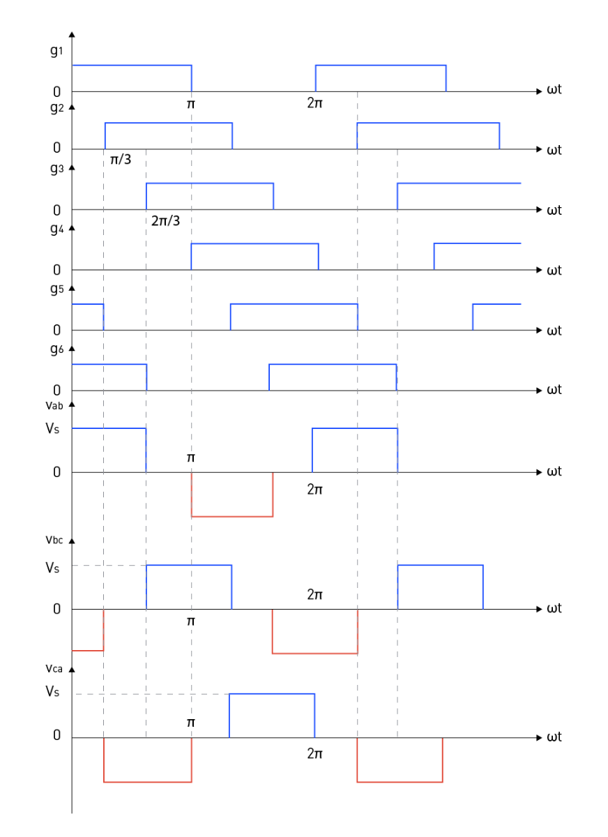
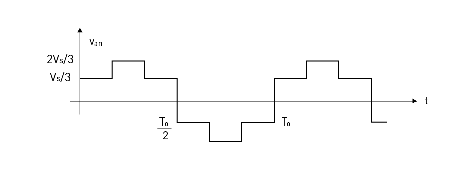
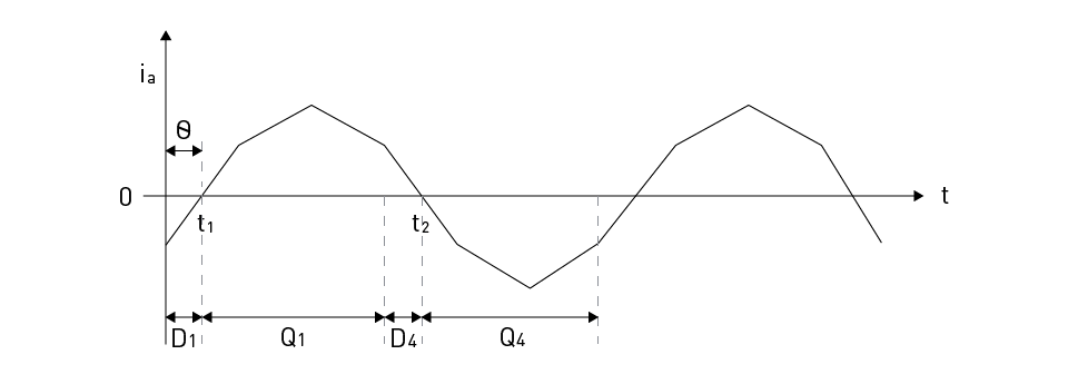
For three-phase applications including motor drives, UPSs, and grid-tied solar inverters, the three-phase full-bridge inverter topology is a frequently used design. The architecture is Figure 19: The Topology of a Three-Phase Full Bridge Inverter The 120-degree conduction mode and the 180-degree conduction mode are the two fundamental operating modes for three-phase full-bridge inverters, respectively. Figure 20: Gating and Phase to Neutral Voltage Waveforms for 120-Degree Conduction Mode Figure 20 depicts the phase to neutral voltages and gating signals when a balanced Y-connected resistive load is used in the 120-degree conduction mode. Transistors conduct in the following order: 61, 12, 23, 34, 45, 56, 61. Every switch conducts for 120-degree. In each phase leg, there are only two switches operating at any given time, and each conducts for a one-third of the fundamental period. The output phase to neutral voltage pattern is simple to understand. To cite an example, consider the initial time interval (0 to π/3) when g1 and g6 are active, causing Vs to emerge across nodes a and b; resulting in Van =Vs/2 and Vbn =-Vs/2. Similar to this, other voltage patterns are easy to extrapolate and comprehend. Figure 21: Gating and Phase to Phase Voltage Waveforms for 180-Degree Conduction Mode Figure 21 displays the phase to phase voltages and gating signals for a balanced resistive load operating in the 180-degree conduction mode. Three transistors are always on at any time and each switch conducts for 180-degree of the fundamental output voltage waveform. The output phase to phase voltage pattern in the 180-degree conduction mode is straightforward to comprehend. Think of the initial time interval (0 to π/3) when g1, g5, and g6 are active, causing Vs to emerge across nodes a and b as well as nodes c and b. This results in Vab = Vs and Vbc = -Vs. Similarly, extrapolating and comprehending other voltage patterns are simple. Likewise, it is possible to calculate the phase to neutral voltages for balanced Y-connected loads from the gating signal patterns, which end up being step square waveforms. The step size is Vs/3 because three transistors are active at once. Consider an example, for the first time period (0 to π/3) where g1, g5, and g6 are on; Vs appears across node a/c and b. Therefore, Van = Vs*(Rl/2)/ (3Rl/2)= Vs/3. Likewise, other voltage patterns can easily be extrapolated and understood as shown for Van in Figure 22. Figure 22: Typical Phase to Neutral Voltages in Three-Phase Inverter Figure 23: Typical Phase Current for Three-Phase Inverter with RL Load It is crucial to note that freewheeling diodes play a crucial role in three-phase inverters with RL loads. According to Figure 23, the current in each inverter arm is delayed to reach its basic voltage. Because current is inductive by nature, it does not change quickly when the voltage polarity is reversed. Take Q1 turning on and a positive load current as an example. Due to the inductive nature of the load current and the fact that D4 provides a conduit for it to flow, the load current does not instantly collapse. Since, the conduction time of transistors and diodes relies on the load power factor, it should be noted that the transistors must be continually gated. Two of the load terminals are connected to the input supply while the third one is left open in the 120-degree conduction mode. The unexpected potential of the open terminal is determined by the load characteristics. The 120-degree conduction mode of each transistor results in underutilization when compared to the 180-degree conduction mode for the identical load state. Due to these reasons, three-phase inverters prefer to operate in the 180-degree conduction mode.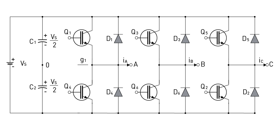
120-Degree Conduction Mode
180-Degree Conduction Mode
120-Degree Vs. 180-Degree Conduction Modes

直接登录
创建新帐号