Magnetic Position and Angle Sensors: Common Types, Key Components, Parameters, Usage Considerations and Applications

Get valuable resources straight to your inbox - sent out once per month
We value your privacy
Introduction
Magnetic position and angle sensors are widely used in a variety of sectors because of its non-contact, wear-free, and sensing capabilities. These devices enable the measurement of linear and angular displacement in a variety of applications ranging from automotive systems and industrial automation to consumer electronics and aircraft. This page discusses the working principles of various kinds, performance metrics, critical components, design considerations, and applications of magnetic sensors.
Common Types of Magnetic Sensors
Magnetic position sensors and angle encoders work by interacting with a magnetic field and a sensing device. A magnetic field is created by either a permanent magnet or an electromagnet, and its intensity changes with the target's location or angular displacement. Sensing components within the devices detect changes in the magnetic field and transform them into electrical signals according to the target's location or angle.
Magnetic position sensors and angle encoders are built with numerous sensor technologies, each with its own set of benefits and drawbacks. We will now go through the many types of magnetic sensors and their fundamental operating principles.
Induction Sensors

Figure 1: Coil Operating Principle
Induction sensors, which are based on Faraday's law of induction, are the most fundamental type of magnetic sensing. It can only detect changes in the magnetic field. Figure 1 depicts the operation of an inductive magnetic sensor coil. When a magnet is brought closer to a coil, the magnetic flux density in the coil rises, resulting in opposing forces in the form of induced electromotive force (emf) and induced current. When the coil stops rotating, the variations in the magnetic flux density stop as well, as do the induced electromotive force and current. The coil's output voltage is proportional to the rate of change of the magnetic field.
Only the rate of change of magnetic flux density and its direction may be calculated using the induced electromotive force. Integration is necessary to calculate the magnetic field density. Coils have limited usefulness; but, when combined with other sensors, they can give important functionality.
Hall Effect Sensors
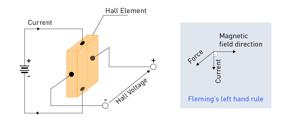
Figure 2: Hall Principle
These sensors are based on the Hall effect, which produces a voltage differential across a conductor when a magnetic field is applied across the cross-section of a current carrying conductor (see Figure 2). The Fleming left-hand rule allows us to calculate the direction of the electromotive force (emf) that is created orthogonally to the current and magnetic field. The magnitude and relative angle of the current and magnetic field assesses the resultant vector voltage proportional to the Hall's constant.
Hall effect sensors are very inexpensive, sturdy, and dust and dirt resistant, although they have poorer sensitivity and resolution than other varieties. These sensors are used in applications such as proximity switching, location, speed detection, and current sensing. The majority of Hall sensors are utilized in automotive applications for position sensors (linear or angular) and contactless DC motors.
Magneto-Resistive (MR) Element Sensors
Magneto-resistive (MR) elements are another prominent form of magnetic sensor. When a magnetic field is applied across an MR element, its resistance varies. Anisotropic magnetoresistive element (AMR), giant magnetoresistive element (GMR), and tunnel magnetoresistive element (TMR) are three popular MR sensor types that use a ferromagnetic thin film material. Because of their reduced noise levels, these sensors often provide superior resolution and accuracy than Hall effect sensors.
Anisotropic Magneto-Resistive (AMR) Sensors
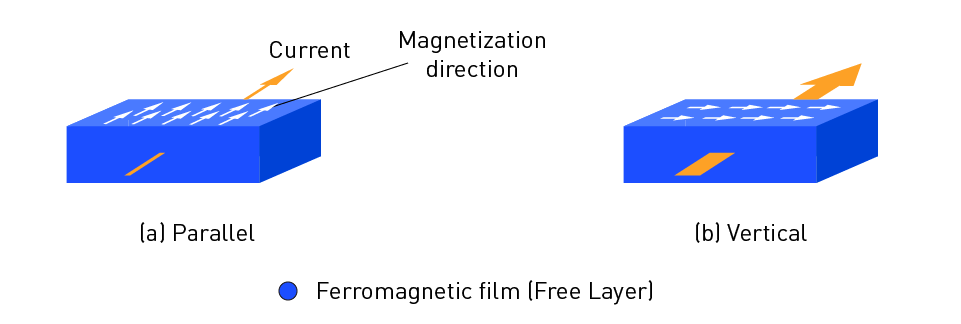
Figure 3: AMR Working Principle
The change in resistance of ferromagnetic materials when exposed to a magnetic field is used by AMR sensors. Figure 3 shows the scattering degree of electro changes when the ferromagnetic film's magnetization direction is parallel to the current direction and when the magnetization direction is vertical to the current direction. As a result, the resistance value changes as well.
The magnetoresistive ratio (MR ratio), which represents the rate of change in resistance induced by the state of the magnetic field, is an important metric in MR sensors. An AMR sensor element has an MR ratio of roughly 5%.
Because of its simple construction, AMR is frequently utilized in magnetic switches and rotation sensors.
Giant Magneto-Resistive (GMR) Sensors
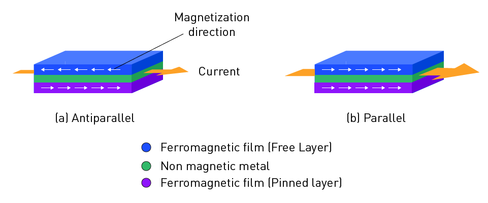
Figure 4: GMR Working Principle
GMR sensors are based on a thin-film construction made of alternating ferromagnetic and non-magnetic layers (see Figure 4). The degree of electron scattering varies depending on whether the magnetization directions of the Ferromagnetic film pinned layer and the free layer are antiparallel or parallel. The resistance value varies as a result of this process.
The MR ratio of GMR sensor elements is roughly 20%. GMR sensor elements are used for magnetic heads, rotary sensors, and other devices due to their increased sensitivity.
Tunnel Magneto-Resistive (TMR) Sensors
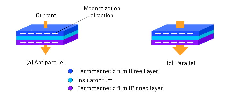
Figure 5: TMR Working Principle
TMR sensors detect magnetic fields by utilizing the quantum mechanical phenomena of tunneling magneto-resistance. Figure 5 depicts the construction utilized in TMR sensors, which consists of a laminated ferromagnetic film (pinned layer), an insulator film, and a ferromagnetic film (free layer). The fraction of electrons traveling through the insulator fluctuates due to the tunneling effect. As a result, the resistance changes depending on whether the pinned layer and free layer magnetization directions are antiparallel or parallel.
TMRs have an MR ratio that can exceed 100%. Because of its high sensitivity, TMR has become the ideal choice for hard disk magnetic heads or high sensitivity rotation angle sensors. MR technology is used in a wide range of applications including magnetic storage, position and angle sensing, navigation, current sensing, non-destructive monitoring, and biomedical sensing systems.
Fluxgate Sensors
Fluxgate sensors are a conventional innovation with several advantages. These feature a high level of sensitivity and resolution. These sensors, however, can be rather massive. It has been demonstrated that fluxgate sensors can be shrunk, although the magnetic resolution suffers as a result. In these sensors, the generated alternating signal, which is modulated by a low-frequency signal, is proportionate to the measured magnetic field, making noise and offset reduction simple. These have been used effectively in geophysics and astronomy, wearable electronic devices, and non-destructive testing.
SQUID (Superconducting Quantum Interference Device) Sensors
SQUIDs are superconducting-based magnetic field sensors with extraordinarily high sensitivity. They can provide very high resolution and precision, but they are restricted by the necessity for cryogenic temperatures and the expensive cost. SQUID sensors are used to monitor very small magnetic fields, often biomagnetic fields.
Other emerging technologies: Recent developments, like printed and flexible sensors, are also being developed to answer particular application demands and provide potential cost, form factor, and integration advantages.
Key Components
Magnetic sensors are made up of several main components that all collaborate together to make them work:
Permanent magnets: These produce the magnetic field needed for sensing. Magnet selection is determined by the application and factors such as magnet size, positioning, shape, strength, and temperature stability. Figure 6 shows the examples of magnet shapes for angle encoders.

Figure 6: Example Magnet Shapes for Angle Sensors
Sensing elements: These sense magnetic field variations and turn them into electrical impulses. Sensing elements include inductive sensing elements, Hall effect, and magneto-resistive elements, among others, each with advantages and disadvantages. Figure 1-5 shows how the sensor components react to an external magnetic field.
Signal conditioning and processing circuitry: This element analyzes the sensing element's raw signals, filtering noise and amplifying the signal as needed. It may also convert signals, such as analog-to-digital conversion.
Communication interfaces: These let the sensor to exchange position or angle data with other devices such as microcontrollers or computers. In addition to analog signal output, common interfaces include analog outputs, digital outputs (such as PWM, SPI, or I2C), and communication protocols (such as CAN bus or Ethernet).
Figure 7 depicts an example block diagram of a magnetic angle sensor.

Figure 7: Example Block Diagram of a Magnetic Angle Sensor
Performance Parameters
Several performance characteristics must be considered when assessing magnetic position sensors and angle encoders:
Sensitivity: It is defined as the output signal to input signal ratio and greater sensitivity is often preferred. The degree of sensitivity is encompassed in the sensitivity constant of a sensor. The sensitivity constant should ideally be constant, however it might vary depending on the measured magnetic field, impacting a sensor's linearity.
Linearity: The proportionality of the output signal to the input signal. To increase accuracy, nonlinearity effects in sensors, such as MR sensors, may necessitate calibration or correction, such as feedback.
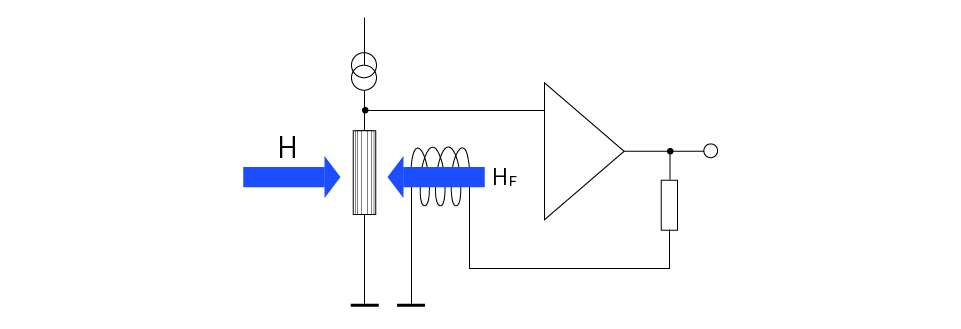
Figure 8: Use of Feedback to Improve Linearity of Magnetic Sensors
Figure 8 demonstrates how magnetic field feedback may be used in magnetic sensors. Because magnetic sensors operate in the zero field range, where the properties are linear, negative feedback can be used to restore linearity. In fact, utilizing the feedback strategy, it is feasible to extend the range of all sorts of sensors.

Figure 9: Improvement of Characteristics of Magnetic Sensors using Feedback
Figure 9 depicts how the magnetic sensors’ characteristics can be restored by introducing feedback.
Hysteresis: When a ferromagnetic material is magnetized, it returns to zero magnetization upon removal of the magnetizing field. In reality, a field in the opposite direction is necessary to push it back to zero. Similarly, when an alternating magnetic field is applied, a so-called hysteresis loop is formed. The lack of retraceability of the magnetization curve is referred to as hysteresis. Low hysteresis is often preferred, as it provides constant readings and improves accuracy. Figure 10 shows a typical hysteresis loop.
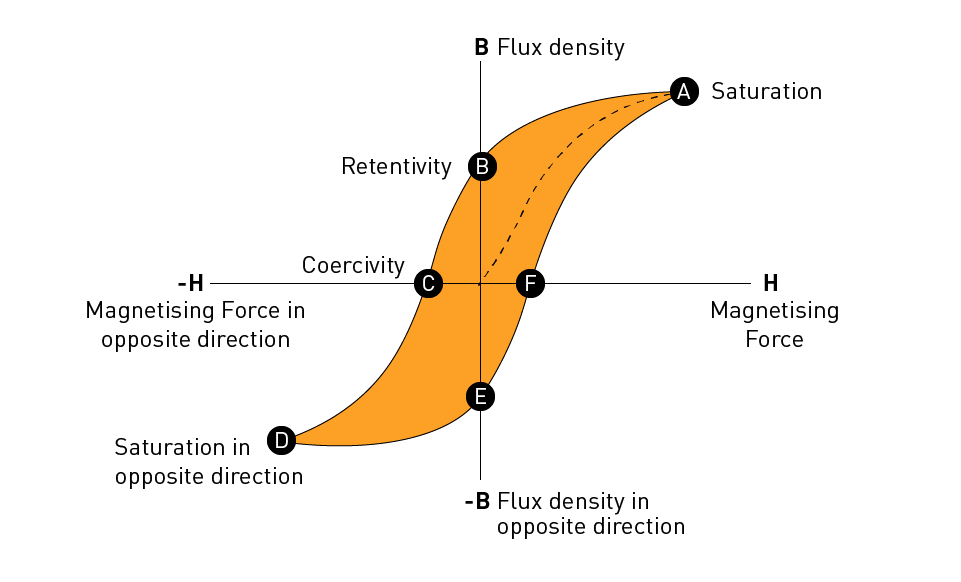
Figure 10: An Example of Hysteresis Loop
Noise: Noise is a critical characteristic of magnetic sensors that is often represented by power spectral density (PSD) or variance. Figure 11 depicts the typical PSD values of MR sensors and Fluxgate sensors over a variety of frequencies.
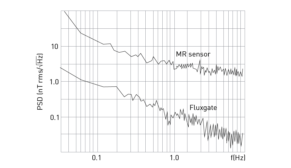
Figure 11: Comparison of PSD of MR and Fluxgate Sensors
Internal noise sources, such as resistance/semiconductor junctions, are common. Electronic circuits contribute to the degree of noise as well. Noise effects can be reduced utilizing signal processing techniques in both the analog and digital worlds. For example, a lock-in amplifier based on the idea of synchronous detection can be employed to pass only signals corresponding to the reference frequency. Figure 12 demonstrates such an amplifier setup for processing fluxgate sensor signals.
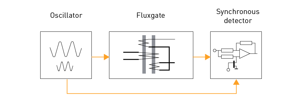
Figure 12: Use of Lock-In Amplifier for Magnetic Sensors
Digital filters can also be used to process noise. However, since filtering takes time to analyze the signal, such as moving averaging filters, this might reduce the sensor's bandwidth.
Measurement Offset: It is a phrase that is closely connected to noise. It is a systematic bias that causes observations to remain consistent over many measurements done under the same conditions, such as temperature drift. Offsets can be reduced utilizing differential techniques such as bridge circuits, differential amplifiers, and so on.

Figure 13: Use of Differential Amplifier to Mitigate Offset in Magnetic Sensors
Figure 13 shows how a differential amplifier can be used to reduce offset in magnetic sensors. Rx represents the resistance of an active sensor, whereas R0 represents the resistance of a second passive sensor. We can reduce the common offsetting impact by affecting Rx and R0. The impact of offset can be negated with the differential output by using the output voltages V1 and V2 to denote the respective output voltages and the output voltage which can be calculated with Equation (1). Furthermore, offset can be reduced utilizing digital signal processing techniques.
$$V_{OUT} = K (V_1 - V_2)$$Bandwidth: When considering sensor performance, one important characteristic that is sometimes forgotten is bandwidth, also known as cutoff frequency. Sensor bandwidth is the frequency range of a signal that can be detected by the sensor. Signals whose frequency exceeds the sensor bandwidth are attenuated. A full characterization of the sensor would necessitate an analytical or graphical representation of its transfer function. At the very least, the cutoff frequency should be specified. A frequent design criterion is that the sensor's output-filter bandwidth (which determines where the sensor is positioned) should be at least 10 times bigger than the control system's bandwidth.
Resolution: The resolution of the sensor is another noise-related metric. It is the smallest change in position or angle that may be detected. Finer motions or rotations can be detected by higher resolution sensors. It is constrained by sensor noise since noise determines how efficiently signal levels can be discriminated without ambiguity. The resolution of sensors with digital outputs is typically measured in bits. For additional information on magnetic angle sensor resolution, click to read this article.
Latency/Response time: It is defined as the amount of time the sensor takes to react to a change in the input signal. Better real-time control and monitoring are enabled by faster reaction times or lower latency. Magnetic sensing devices for latency correction and error reduction during sensing can be designed.
Temperature range and stability: The sensor's operating temperature range and its ability to retain accuracy and performance across that range. Temperature has an effect on all magnetic sensors in practice. Temperature-compensated sensors, on the other hand, are achievable with the right design.
Usage Considerations
Several issues must be considered when designing systems based on magnetic position sensors or angle encoders.
Sensor selection based on application requirements: Select the right sensor type depending on factors such as sensitivity, linearity, resolution, bandwidth, temperature range, and so on.
Magnet selection and placement: To achieve best performance and accuracy, choose the right magnet type, size, and location.
Environmental factors: Consider temperature, humidity, and vibration, which can all have an impact on sensor performance and dependability.
Interfacing with microcontrollers or other electronics: Choose relevant interfaces to allow for easy integration with other system components. These can be direct analog outputs or digital outputs with a suitable communication link.
Calibration and Testing
Magnetic position sensors and angle encoders must be calibrated and tested properly to ensure precise and dependable operation.
Calibration methods and procedures: To account for non-linearities and increase accuracy, use appropriate calibration techniques such as zero-point calibration, gain calibration, or curve fitting. Other user-controlled factors, such as digital filtering settings, should also be appropriately established.
Testing for accuracy, repeatability, and reliability: Test the sensor's performance under various situations, such as temperature, humidity, and vibration. To guarantee consistent performance, evaluate measurement repeatability and long-term dependability.
Applications
Magnetic position sensors and angle encoders are widely used in many sectors, including:
Intelligent Transporation
These sensors are important in applications such as throttle position, steering angle, gear position, suspension control sensors, and electric motor control. Figure 14 illustrates how magnetic angle sensors can be used in e-bikes. Angle sensors provide wake-on-angle sensing for throttle and gear shifters in idle mode. When the sensor detects an angle or motion, it transmits an interrupt to the system. This provides for improved energy management because the system is only enabled when the sensor is triggered.
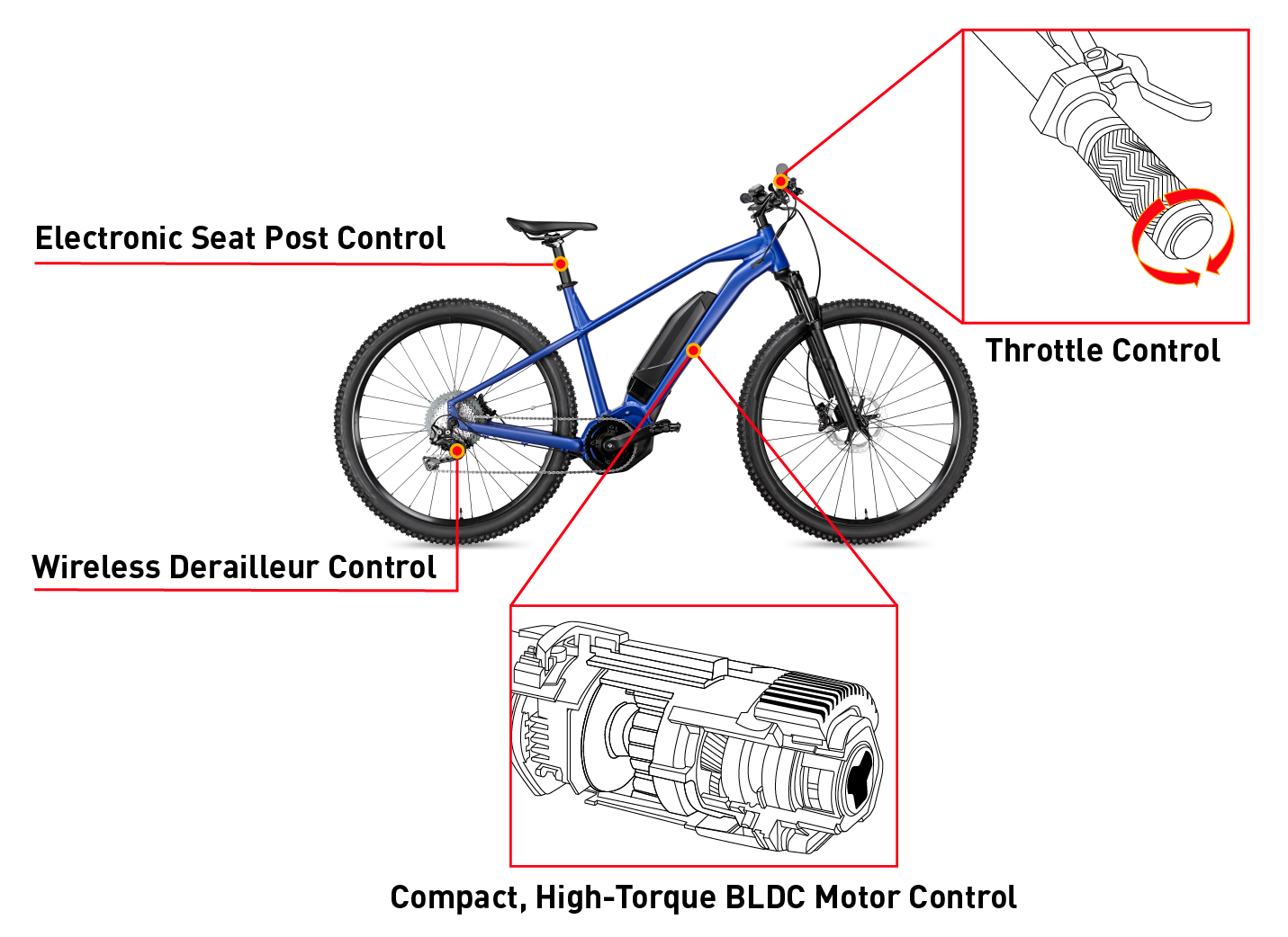
Figure 14: Application of Magnetic Angle Sensors in Intelligent Transportation
Industrial Automation
Industrial Automation: Magnetic position sensors and angle encoders are used for accurate positioning and control in robotics, conveyor systems, linear and rotary encoders, and automated manufacturing equipment. Figure 15 shows how magnetic angle sensors are used in robotics applications, such as a robotic arm. This enables accurate movement control by determining the location of the drives of the robotic control systems.
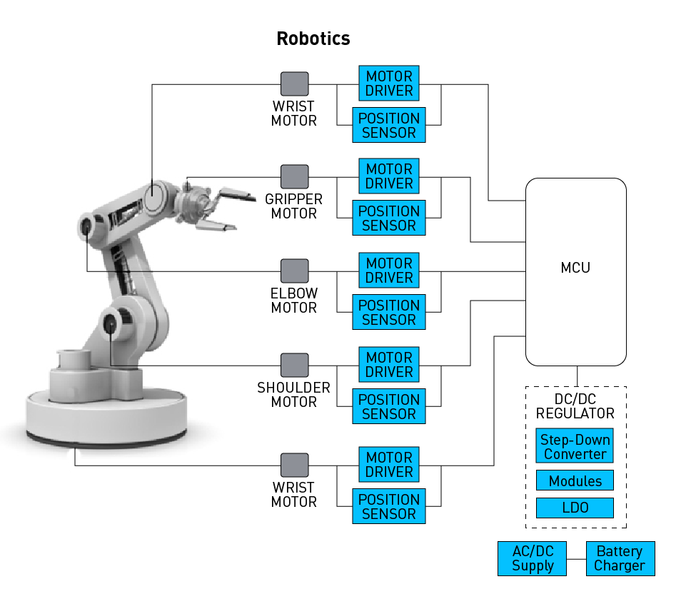
Figure 15: Application of Magnetic Angle Sensors in Robotics: Robotic Arm
Consumer Electronics
These sensors are integrated into smartphones, tablets, gaming consoles, and wearables for a variety of functions such as screen rotation, joystick control, and motion tracking. See figure 17 and 18 for magnetic angle sensors in smartphones and tablets. Angle sensors with low power, extended battery life, minimal solution size, and rotational precision enhance flexible screens in foldable phones. Modern angle sensors, as opposed to the classic magnet method on the bezel, enable for accurate angle detection on the side of the hinge, which is important for new, foldable phone designs.
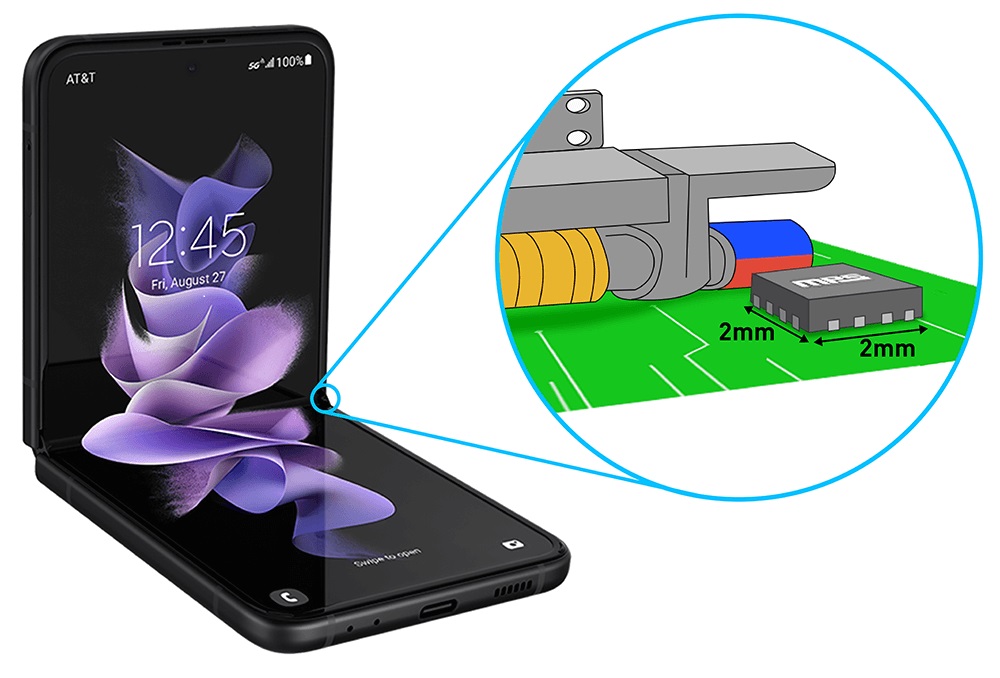
Figure 16: Application of Magnetic Angle Sensors in Consumer Electronics: Foldable Smartphone
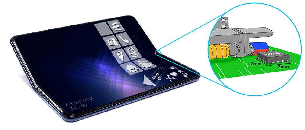
Figure 17: Application of Magnetic Angle Sensors in Consumer Electronics: Foldable Tablet
Industrial Electronics
Magnetic position sensors and angle encoders are used in a wide range of industrial electronics equipment, including conveyor belts, rotary devices, and process plants, and many more. Figure 19 depicts an industrial use for angle sensors, such as a drill machine. Magnetic angle sensors are required to commutate the motor with a specific angular accuracy. Figure 20 demonstrates how magnetic position sensors may be used to assess position in rack gear to determine how much movement has occurred from a certain location.

Figure 18: Application of Magnetic Angle Sensors in Motor Control Industrial Applications: Drill Machine
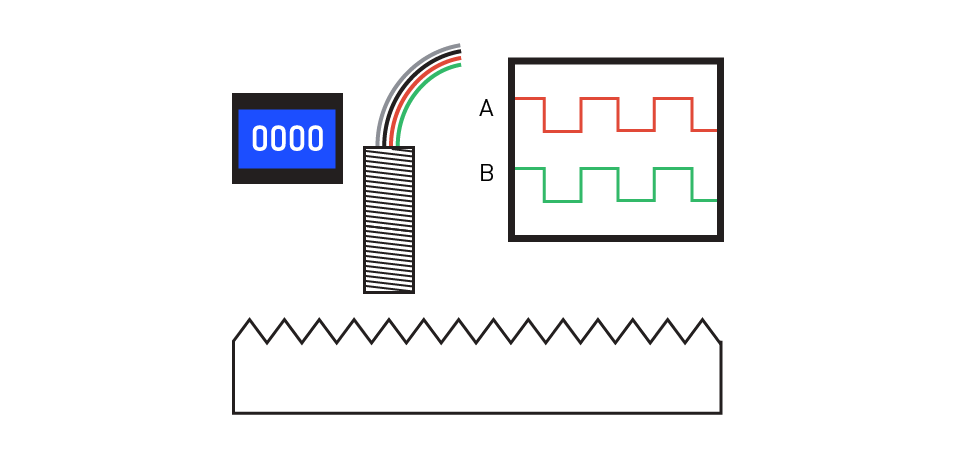
Figure 19: Application of Magnetic Position Sensors in Industrial Applications: Position Detection in Rach Gear
Conclusion
Magnetic position sensors and magnetic angle encoders are used in a variety of applications across several industries. This page includes an overview of their operating principles, widely used kinds, major components, performance characteristics, usage concerns, and applications. As technology advances, we should expect significant advancements in sensor performance, new sensor technologies, and an expanding spectrum of applications.
MPS sensors offer cutting-edge performance and adaptability for angular motion control and position sensing applications. To get more information on magnetic encoders, visit our angular position sensor page.
_______________________
Did you find this interesting? Get valuable resources straight to your inbox - sent out once per month!
技术论坛
 Latest activity 4 weeks ago
 11 回复
11 回复
 Latest activity 4 weeks ago
 21 回复
21 回复
 Latest activity 2 months ago
 16 回复
16 回复


直接登录
创建新帐号