Powering FPGAs with Dual-Output Modules

DOWNLOAD PDF

Get valuable resources straight to your inbox - sent out once per month

Subscribe

We value your privacy

Introduction

The increasing demand across telecommunication systems, data storage, and field-programmable gate arrays (FPGAs) has driven the evolving complexity and requirements of power delivery, particularly for voltage regulators (VRs). Most areas of VR applications require a balance between efficiency, I/O voltage range, voltage tolerance, and size. It is crucial to meet the demands of FPGA power rails while providing precise voltage control.

With the increased number of power rails, designers must find solutions for both high-current and low-current rails. Multiple-phase power supplies achieve higher current delivery with reduced inductor size requirements, and multiple-output power supplies allow designers to power several FPGA rails with a single IC. As a result, designers can meet all the modern requirements for power delivery with reduced board space and simplified design.

This article discusses using multiple-output power supplies to meet the FPGA power rail requirements with the MPM54322, a dual-output power module. Key considerations for powering FPGAs include voltage rail regulation as well as proper start-up and safe shutdown of FPGA power rails.

FPGA Voltage Rail Regulation

Load Transients and Voltage Ripple

Modern field-programmable gate array systems require a higher number of power rails with varying voltage and current requirements. Advanced FPGA designs often require up to 8 power rails depending on the features of the FPGA, such as double data rate (DDR) memory, high-speed transceivers, or any other peripheral devices. Most FPGA-based systems are supplied with a 12V bus, and the required voltages of the different FPGA power rails vary between 0.65V and 3.3V.

Voltage ripple tolerance is the primary objective of power supply design as one of the strictest regulations for powering FPGAs. The tolerance is specified in the manufacturer’s datasheet, but generally the voltage ripple tolerance must not exceed ±3% of the rated voltage or ±30mV.

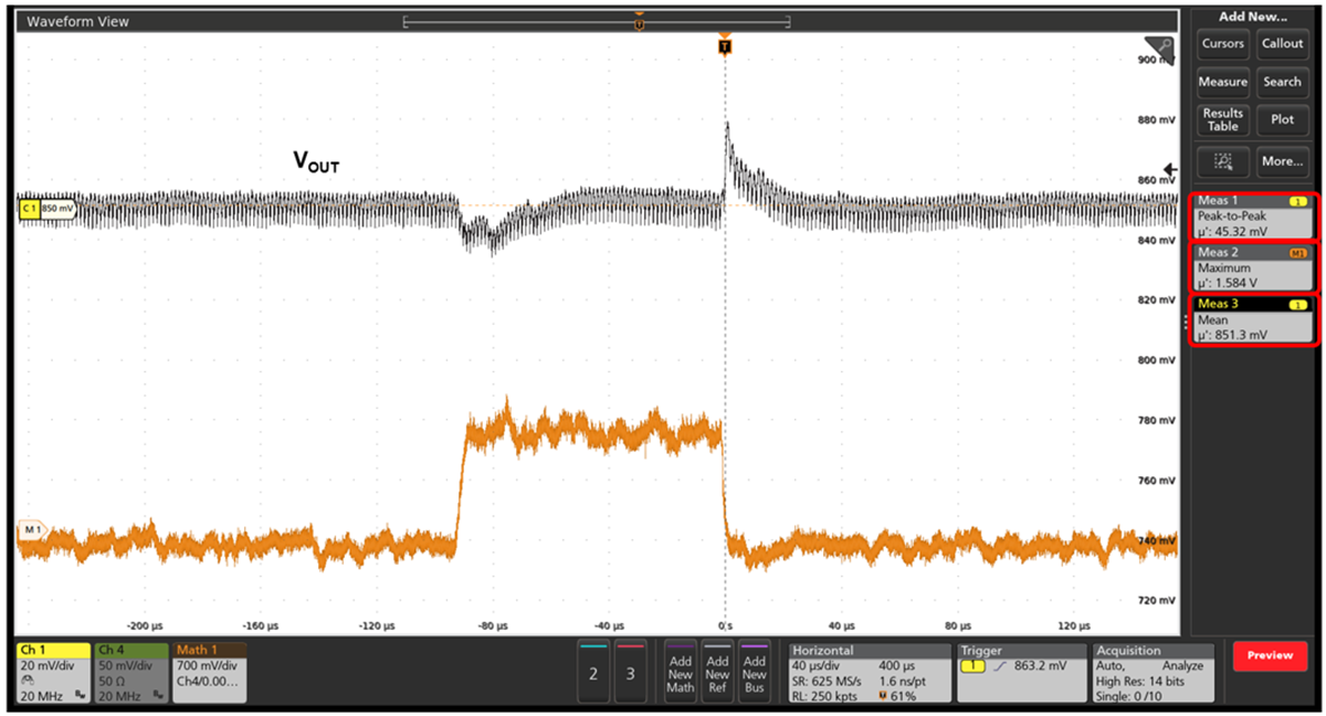
The complexity of meeting such requirements can be demonstrated with a load transient test that was conducted with the MPM54322, a 3A, dual-output power module. To better emulate the behavior of the FPGA, transients were generated using a load slammer, which performs load steps with very high slew rates up to 130A/µs.

In the load transient test, the load steps up from 0A to 1.5A and is powered by one of the module’s 3A outputs. This test was carried out with an input voltage (VIN) of 12V and an output voltage (VOUT) of 0.85V to emulate the most common core power rails of modern FPGA designs (see Figure 1).

Figure 1: 0A to 1.5A Load Transient with Slammer Load

The load transient test demonstrates excellent transient response with ±22.5mV voltage peaks during the 130A/µs transitions. In addition, the output voltage ripple is within the FPGA core rail’s tolerance requirements due to MPS’s adaptive constant-on-time (COT) control. By using COT control, the power supply delivers the required energy to the load much quicker than traditional peak current mode control. As a result, stable voltage can be maintained during power transients without requiring high output capacitance.

Start-Up and Shutdown Sequencing

Field-programmable gate array applications have multiple power rails connected to multiple voltage regulators. During the board’s start-up, a set order for starting up the rails must be maintained to optimize system efficiency and minimize start-up current peaks. However, implementing a sequencer might not be a feasible option since the board space can be very limited. Multiple-output power modules such as the MPM54322 use MPS-patented FLEX-timer sequence control, which allows accurate control of the start-up and shutdown timing of all VRs without a sequencer.

Ensuring Proper Start-Up

Soft-Start Control

Soft start (SS) is a critical requirement for FPGA power rails to ensure reliable start-up and prevent potential damage to the device. This feature is implemented in voltage regulators that control the VOUT rise time during start-up. This is particularly important for FPGA design due to their large capacitive load on the power rails. Without SS, the inrush current during start-up can be very high, potentially causing voltage droop on the input supply and damage to the FPGA or other components.

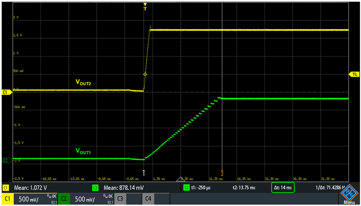
Most FPGA vendors specify a SS time (tSS) of about 10ms for their devices. By increasing the voltage gradually with tSS, the inrush current is limited, and a smooth start-up sequence is achieved. Failure to meet the SS requirements can lead to various issues, such as unreliable or non-monotonical start-up and potential damage to the FPGA.

To ensure reliable operation, it is crucial to select VRs that meet the SS requirements specified by the FPGA vendor. Regulators like the MPM54322 provide an adjustable tSS that can be finetuned to the specific requirements of the FPGA and power supply design.

The MPM54322 can have tSS as short as 1ms and as long as 14ms in the start-up sequence (see Figure 2).

Figure 2: Start-Up Sequence with Two Independent Rails

MPS-Patented FLEX-Timer Sequence Control

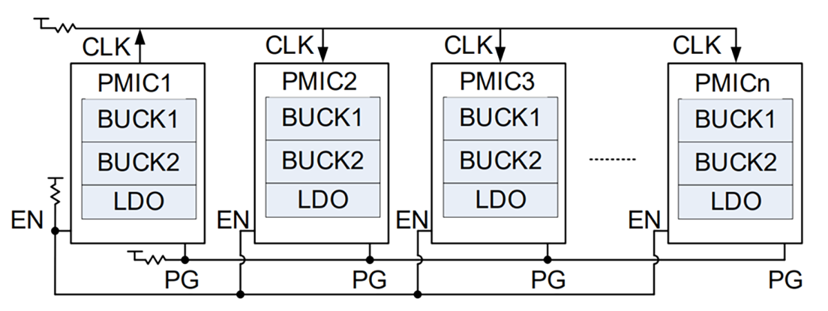
The MPM54322 uses FLEX-timer sequence control to better control the order in which the different power rails are initiated. This sequence control scheme uses a master-slave structure where the control signals of all the power management ICs (PMICs) are connected for sequence coordination (see Figure 3).

Figure 3: FLEX-Timer Sequence Control

One of the PMICs is configured as the master to generate a clock signal, while the other PMICs are configured as slaves that receive the clock signal. The start-up and shutdown sequences of all the power rails are synchronized by the clock signal.

When the control signal is asserted, the start-up sequence begins with the master PMIC generating the clock outputs and the slave PMICs counting the clock signal. For each power rail, the rail turns on when the counted clock signal cycle reaches a pre-defined delay.

Once the master PMIC clock cycle reaches a preset number and a status signal indicates all enabled power rails have finished the SS process, the master PMIC stops the clock output, and the start-up sequence completes.

During shutdown, if the control signal is not present, the master PMIC starts generating the clock outputs, and the slave PMICs count the clock signal. For each power rail, the rail turns off when the counted clock signal cycle reaches a pre-defined delay. When the master PMIC clock cycle reaches the set number, the master PMIC stops the clock output, and the shutdown sequence finishes.

This sequence control scheme provides a synchronized and coordinated start-up and shutdown process across multiple power rails managed by different PMICs without introducing an additional sequencer module.

Ensuring Safe Shutdown Using Active Discharge

VOUT spikes can severely damage the FPGA through the power rails. When the load is suddenly removed, the energy stored inside the output capacitors (COUT) can cause high voltage spikes while discharging. To prevent these hazards, the MPM54322 implements the output’s active discharge.

The purpose of active discharge is to quickly discharge a PMIC’s COUT when the load is suddenly removed or the power turns off. Since FPGA power modules use large decoupling capacitors for stability and optimal voltage regulation, active discharge helps quickly discharge these capacitors, preventing voltage spikes while maintaining the proper shutdown sequence and timing.

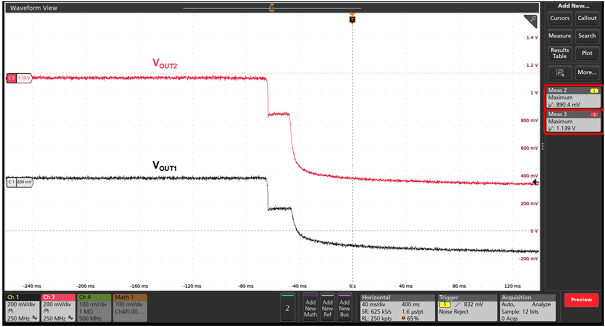
Active discharge is performed when the part is disabled and the output of the internal digital-to-analog convertor (DAC) ramps down. VOUT ramps down smoothly with the reference voltage. When the DAC output reaches 850mV and 650mV, it stops at these levels and soft shutdown completes. The output then gradually discharges through the feedback resistors.

Figure 4 shows the shutdown sequence of the MPM54322.

Figure 4: Shutdown Sequence of the MPM54322

Introducing the MPM54322

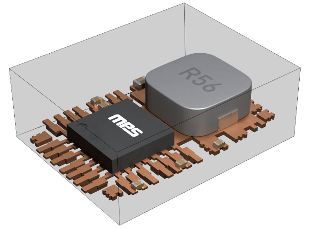
MPS offers a wide selection of flexible and scalable multiple-output power modules. The MPM54322 is a 3A, dual-output power module that integrates two high-efficiency, step-down DC/DC converter ICs, a low-dropout (LDO) regulator, and passive components (including two inductors for the DC/DC converters) onto a single over-molded package. The MPM54322’s two outputs can be used separately to power the two independent rails of the field-programmable gate array, or they can be paralleled for up to 6A of current.

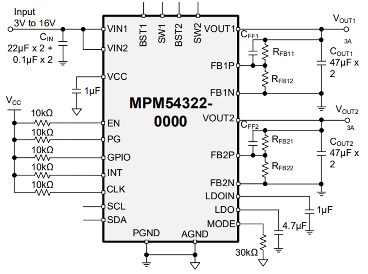
Figure 5 shows the typical application circuit of the MPM54322.

Figure 5: Typical Application Circuit of the MPM54322

As previously discussed, FPGA systems include many rails for separate systems not related to FPGAs. The same multiple-output power modules can be used to start up other subsystems as well. Given the varying voltages and currents, using parts differentiated with digital suffixes can result in problems during production and the set-up process, causing potential damage to the FPGAs. To address this issue, the MPM54322 provides up to 10 multiple-time programmable (MTP) pages (determined by the resistor connected to the MODE pin), allowing the user to switch between preset adjustable configurations for different voltages.

Conclusion

With the increasing power requirements of FPGAs, advanced multiple-output VRs are necessary for designing power supplies with reduced board space that can keep pace with advanced FPGA applications.

Advanced power supplies like the MPM54322 enable fast transient response and accurate voltage regulation, in addition to featuring SS and MPS-patented FLEX-timer sequence control to ensure safe system start-up and shutdown. Furthermore, as systems become more complex, the MPM54322 allows the designer to easily select among the 10 MTP pages for different output configurations using the same device, without having to re-configure or use different part numbers.

For more information, explore MPS’s full portfolio of power modules.

_______________________

Did you find this interesting? Get valuable resources straight to your inbox - sent out once per month!

获取技术支持