Optimizing Home Remote Controls with MPS Products

Get valuable resources straight to your inbox - sent out once per month
We value your privacy
Introduction
Infrared (IR) and remote frequency (RF) home remote controls are being used in systems such as sound systems, televisions, lighting, and other controls. These systems are becoming increasingly complex with features including voice control, connectivity, LED displays, and capacitive touch. Remote controls should be reliable, easy to use, and have a long battery lifespan.
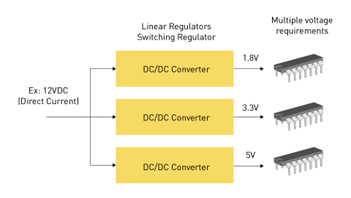
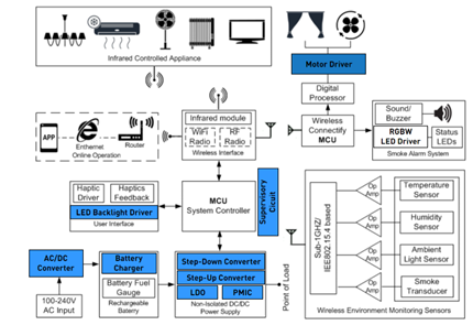
MPS provides cost-effective solutions that can be used to address home remote controls systems throughout the entire system (see Figure 1). MPS solutions that optimize remote home controls — denoted in blue in Figure 1 — are motor drivers, LED backlight drivers, supervisory circuits, AC/DC converters, battery chargers, step-down converters, step-up converters, LDOs, and PMICs. This article will describe each of these components and how they can be used to help design a home remote control.

Figure 1: Application Block Diagram for Remote Home Controls
Motor Driver
A motor driver is an electronic device that controls the speed, direction, torque, and other parameters of an electric motor. It acts as an interface between the motor and a microcontroller unit (MCU) or another control system. Motor drivers are essential components in many applications, including robotics, automation, electric vehicles, and home appliances.
Motor drivers work by:
- Amplifying electrical signals to power and control the motor.
- Regulating the power supplied to the motor.
- Preventing over-current (OC) conditions and motor burnout.
Motor drivers typically include an MCU or dedicated driver IC, power transistors, and protection circuitry. There are many types of motor drivers, including brushed DC motor drivers, brushless DC (BLDC) motor drivers, and stepper motor drivers.
For fans or curtains, a motor driver can be used to make adjustments based on user commands. These adjustments include speed (e.g. slowing down a fan), direction, and position (e.g. closing or opening curtains).
A motor driver should provide precise control to improve user experience and energy efficiency while providing smooth operation and low standby power to extend battery lifespan.
Apart from control, motor drivers provide the necessary power for the motors of these applications to operate, which a microcontroller cannot. MPS has a range of motor drivers for BLDC and stepper motors.
The MP6539 is a gate driver IC designed for three-phase, brushless DC (BLDC) motor driver applications. It can drive three half-bridges consisting of six N-channel power MOSFETs up to 100V (see Figure 2).
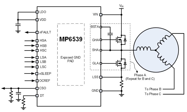
Figure 2: MP6539 Typical Application Circuit
The MP6539 is available in TSSOP-28 (9.7mmx6.4mm) and QFN-28 (4mmx5mm) packages with an exposed thermal pad.
LED Backlight Driver
Within a user interface, an LED backlight driver powers and controls LED backlighting for an LCD or similar display. It ensures consistent brightness and color, adapts to ambient lighting conditions, and minimizes power consumption. This is especially useful in battery-operated devices, as unregulated power consumption can drain the battery more quickly.
LED backlight drivers work by:
- Extending the life of LEDs.
- Optimizing LCD screen performance while providing high color accuracy.
- Ensuring uniform backlight distribution.
- Enabling dimming capabilities.
MPS offers robust, cost-effective LED drivers to address commercial, industrial, and automotive lighting needs.
The MP3318 is a WLED step-up converter that uses peak current mode control to regulate the LED current (ILED) set by the internal registers. Its maximum LED voltage (VLED) is up to 38V, and it can drive 10 LEDs in series for LCD panel applications larger than 5”. In addition, it supports linear and exponential analog dimming with 11-bit, ultra-high resolution to accurately regulate the dimming current (see Figure 3).
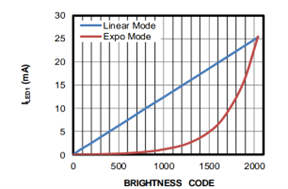
Figure 3: LED Brightness
Full protection features include LED open and short protection, cycle-by-cycle current-limit protection, and thermal shutdown. The I2C interface allows the MP3318 to flexibly set parameters such as protections thresholds, the dimming mode, and the LED current ramp. Figure 4 shows the MP3318’s typical application circuit.
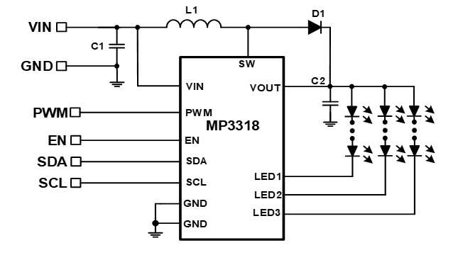
Figure 4: MP3318 Typical Application Circuit
The MP3318 is available in a tiny WLCSP-12 (1.3mmx1.7mm) package.
Supervisory Circuit
For an MCU, a supervisory circuit monitors power supply conditions and ensures that the MCU operates within a safe voltage range, utilizing safety functions such as brownout detection and reset. The supervisory circuit enhances reliability by preventing the MCU from malfunctioning during power disturbances, which guarantees reliable user interactions and responsiveness.
Supervisory circuits work by:
- Ensuring that the MCU operates within its specified voltage range.
- Automatically generating a reset signal if the supply voltage falls below a defined threshold (e.g. brownout detection).
- Resetting the MCU if it becomes unresponsive or enters an undefined state.
- Ensuring that the MCU restarts correctly after a power failure.
These circuits are essential for maintaining system reliability, preventing damage, and ensuring the proper functioning of MCUs in critical applications.
MPS offers a variety of supervisory circuits for home automation devices. The MP6400 family are microprocessor (µP) supervisory circuits. The reset voltage can be factory-set for standard voltage rails between 0.9V and 5V, while the MP6400DG(J)-01 reset voltage can be adjusted with an external resistor divider for added flexibility (see Figure 5).
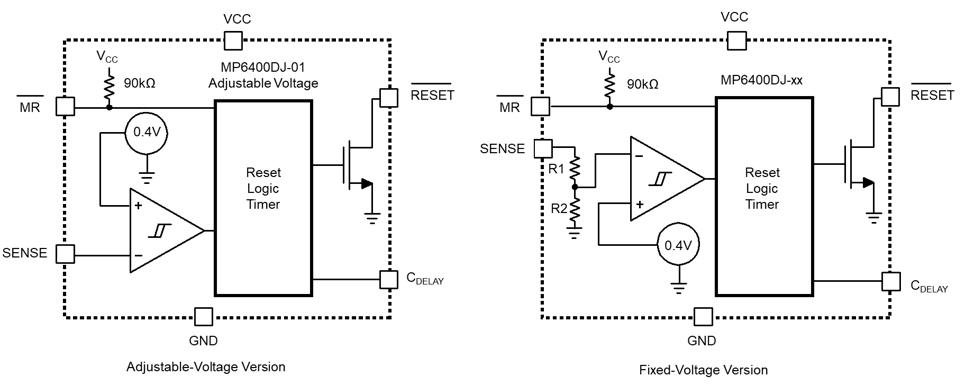
Figure 5: MP6400 Functional Block Diagram
When the SENSE voltage (VSENSE) exceeds its threshold, it is driven to logic high after a user-configurable delay time. It provides a precision reference to achieve ±1% threshold accuracy. The reset delay time can be set from 2.1ms to 10s with a capacitor connected between the CDELAY and GND pins. The MP6400 has a very low quiescent current (IQ) of 1.6µA, which makes it ideal for battery-powered applications. The MP6400 is available in QFN-6 (2mmx2mm) and TSOT23 packages.
AC/DC Converter
An AC/DC converter converts the household AC power to a DC voltage that can power the remote control or charge its battery. An ideal AC/DC converter should provide high efficiency in a compact design, reduce power loss, and ensure compliance with energy regulations. AC/DC converters are widely used in applications such as power supplies for electronics, battery charging, electric vehicles, and renewable energy systems.
AC/DC converters work by:
- Using diodes or controlled switches to convert the AC input into pulsating DC voltage.
- Employing capacitors and inductors to filter and smooth the pulsating DC voltage into a stable DC output.
- Maintaining a constant DC VOUT, regardless of variations in the AC input voltage or output load conditions.
- Providing protections to the connected devices, such as under-voltage protection (UVP) and under-voltage lockout (UVLO).
These converters ensure compatibility between AC power sources and DC-powered devices, enabling efficient energy conversion and reliable operation. MPS provides a wide range of products for AC/DC conversion.
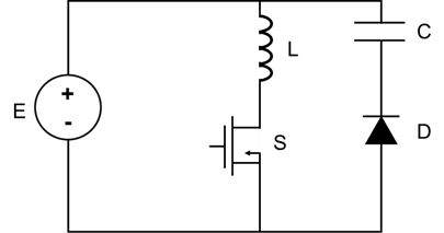
The HFG610-65 is a quasi-resonant (QR) flyback regulator with integrated GaN HEMT with advanced protection features including UVLO, primary-sense output over-voltage protection (ZCD OVP), and primary-sense output UVP (ZCD UVP) (see Figure 6)..
The device is a secondary-side regulation (SSR) based primary regulator with a higher frequency to shrink the passive component size and achieve higher power density. It also provides overload protection (OLP) to protect against a continuous over-current condition that could cause overheating.
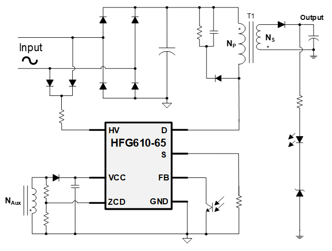
Figure 6: HFG610-65 Typical Application Circuit
The HFG610-65 is available in a QFN-25 (7mmx7mm) package.
Battery Charger
A battery charger safely charges rechargeable batteries, such as the remote control’s battery, by managing current and voltage to prevent overcharging. Battery chargers help reduce waste by encouraging the adoption of reusable batteries, and accurate charging algorithms can further optimize battery lifespan.
Battery chargers work by:
- Delivering the appropriate voltage and current to charge the battery without causing damage.
- Detecting the battery’s charge level, temperature, and status to optimize the charging process.
- Incorporating protection mechanisms into the system, such as OVP and over-temperature protection.
Battery chargers maintain the functionality and longevity of rechargeable batteries in devices ranging from smartphones to electric vehicles (EVs). MPS provides easy-to-use, configurable battery management solutions, which utilize proprietary silicon technology to achieve a high level of integration and excellent thermal performance.
The MP2615D is a monolithic switching charger for 1-cell lithium-ion or lithium-polymer battery packs with built-in power MOSFETs, and is available in a QFN-16 (3mmx3mm) package (see Figure 7). To ensure safe operation while optimizing charging, the MP2615D monitors the battery temperature and charging status for each condition.
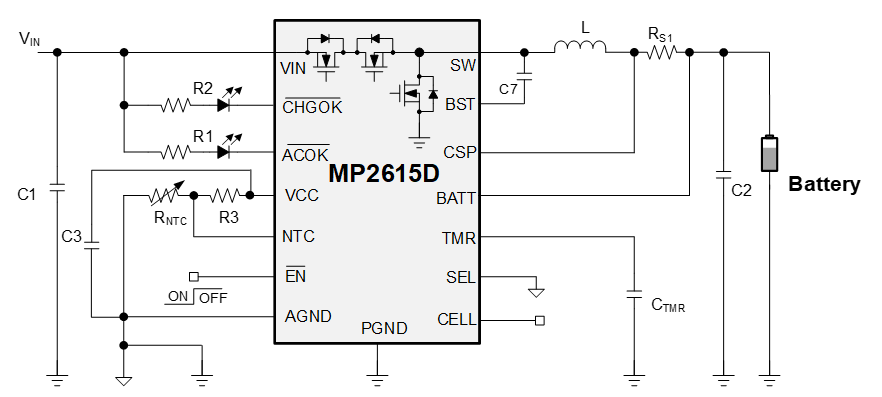
Figure 7: MP2615D Typical Application Circuit
No external reverse-blocking diodes are required to stop the reverse flow of current. The charger features ±0.75% battery-full voltage (VBATT_FULL) accuracy, a configurable safety timer, and preconditioning for a fully depleted battery to prevent battery damage. In addition, it features up to 99% duty cycle operation. The MP2615D provides thermal shutdown protection with a battery temperature monitor to protect the cells from overheating.
Non-Isolated Power Supply
Step-Down Converter
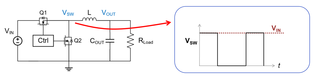
Within a non-isolated power supply, a step-down converter converts a higher voltage (e.g. from batteries or an AC/DC input) to a lower voltage that can power the MCU sensors and points-of-load (PoLs). It improves power efficiency by reducing heat and energy loss, which also helps extend the battery lifespan and can protect devices that receive its output voltage.
Step-down converters work by:
- Using a high-frequency switching element (typically a transistor) and a diode to control the input voltage (VIN).
- Utilizing an inductor and capacitor to store and release energy, which smooths VOUT.
- Adjusting the duty cycle of the switching element to regulate VOUT.
- Providing high conversion efficiency by minimizing power loss.
Step-down converters power low-voltage electronic circuits and devices from higher-voltage power sources. MPS offers many options for buck converters for home automation applications.
The MP8886 is a dual-phase, dual-output, high-efficiency, synchronous step-down converter with a PMBus control interface (see Figure 8). The PMBus and multiple-time programmable (MTP) memory provide flexible configurations for parameters such as the output voltage (VOUT), selectable advanced asynchronous modulation (AAM) mode or forced continuous conduction mode (FCCM), and protection thresholds.
VOUT can be set between 0.6V and 24V. The MP8886 achieves up to 3A of continuous output current (IOUT) for two channels, or up to 6A of continuous IOUT for a single channel, across a wide VIN range. If needed, multiple ICs can be paralleled to achieve an IOUT up to 36A. Full protection features include VIN under-voltage lockout (UVLO) protection, over-voltage protection (OVP), over-current protection (OCP), and thermal shutdown.
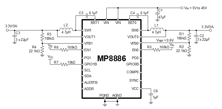
Figure 8: MP8886 Typical Application Circuit
It is available in a TQFN-26 (5mmx5mm) package.
Step-Up Converter
Within a non-isolated power supply, a step-up converter boosts a low battery voltage to a higher level required by specific components, such as MCUs, PoLs, or high-power LEDs. It provides consistent performance even when the battery voltage drops, which extends the battery’s usable life.
Step-up converters work by:
- Employing a high-speed switching element (e.g. a transistor) and a diode to manage VIN.
- Using an inductor to store energy during the switching cycle and release at a higher voltage.
- Adjusting the duty cycle of the switching signal to regulate VOUT.
- Achieving higher output voltages by dynamically controlling the energy transfer process.
Step-up converters are vital for applications requiring higher operating voltages than the available input. MPS provides high-efficiency boost converters for a wide array of applications.
The MP3416 is a step-up converter that works in peak current control mode and provides excellent transient response. Its integrated P-channel synchronous rectifier (SR) eliminates the need for a Schottky diode, which further simplifies the end solution. The MP3416 can work with a VIN as low as 0.86V to provide a 1.8V to 5.5V VOUT range.
Under light loads, the peak current drops to about 350mA, and the device enters pulse-skip mode (PSM) to reduce power loss. The device features over-temperature protection, with thermal shutdown at 155°C. Figure 9 shows the MP3416’s typical application circuit.
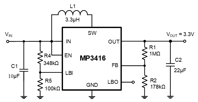
Figure 9: MP3416 Typical Application Circuit
The MP3416 is available in TSOT23-8 and QFN-8 (1.5mmx2mm) packages.
Low-Dropout (LDO) Regulator
Within a non-isolated power supply, a low-dropout regulator (LDO) converts a higher VIN to a lower VOUT to power low-voltage components. Unlike switching regulators, LDOs provide a linear, noise-free output. LDOs enhance the performance of sensitive analog and RF circuits. LDOs are especially useful when the voltage difference between the input and output is small.
LDO regulators work by:
- Using a control circuit and a pass transistor to maintain a constant VOUT.
- Offering a clean, low-noise power output.
- Providing built-in thermal shutdown protection to prevent overheating.
- Safeguarding against excessive current draw to ensure reliable operation.
LDO regulators are recommended when simplicity, low noise, and compact design are critical. MPS’s low-dropout regulators are an excellent fit for lower-current automotive subsystems that need to minimize battery drain.
The MP2015A is a linear regulator that supplies power to systems with high-voltage batteries. The device’s low IQ and low dropout voltage allow for operation at extremely low power levels, which makes it well-suited for MCUs and battery-powered devices. In addition, the MP2015A provides a wide variety of fixed-VOUT options: 1.8V, 1.9V, 2.3V, 2.5V, 3V, 3.3V, 3.45V, and 5V. It also provides an adjustable-VOUT option from 1.215V to 15V (see Figure 10).
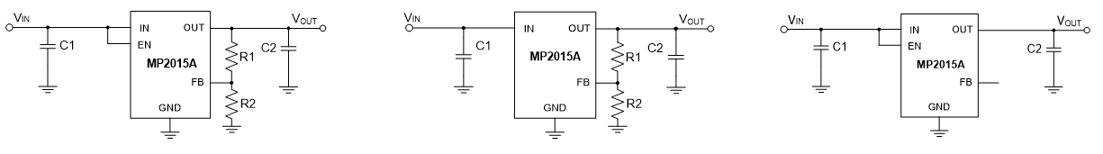
Figure 10: MP2015A Typical Application Circuit (Different Variations)
The MP2015A also includes thermal shutdown and current limiting fault protection, and is available in QFN-6 (2mmx2mm), QFN-8 (3mmx3mm), and TSOT23-4 packages.
Power Management IC (PMIC)
Within a non-isolated power supply, a PMIC integrates multiple power functions (e.g. step-up, step-down, and control) into a single IC. A PMIC reduces PCB size and component count, simplifies design, and improves overall system efficiency. In the unlikely event of a PMIC failure, the time to address the issue is also significantly reduced, as it does not require testing multiple components throughout the system.
PMICs work by:
- Providing multiple regulated power outputs using integrated buck, boost, or linear regulators.
- Ensuring that different components of a system are powered up or down in the correct order.
- Managing power delivery to subsystems and peripherals.
- Supporting energy-saving modes (e.g. sleep and standby mode) to extend battery life.
PMICs are often used in complex, modern electronics that require high power density. MPS’s PMICs and multi-output product families include integrated buck converters, boost converters, buck-boost converters, e-fuses, load switches, and linear regulators.
The MP5416 integrates four high-efficiency, step-down, DC/DC converters, five LDOs, and a flexible logic interface (see Figure 11). The constant-on-time (COT) control scheme for the DC/DC converters provides fast transient response. In addition, the MP5416’s power-on/off sequence can be configured via the one-time programmable (OTP) memory, or it can be controlled through the I2C bus online. Full protection features include under-voltage lockout (UVLO), over-current protection (OCP), and thermal shutdown.
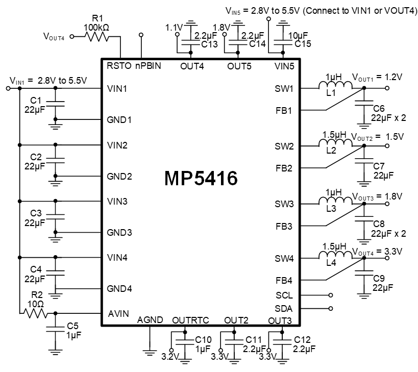
Figure 11: MP5416 Typical Application Circuit
It is available in a QFN-28 (4mmx4mm) package.
Conclusion
This article described the functions of motor drivers, LED backlight drivers, supervisory circuits, AC/DC converters, battery chargers, step-down converters, step-up converters, LDOs, and PMICs in home remote control systems. It also introduced MPS devices that can be used to optimize home remote control from each of these categories.
MPS components within a home remote control enable users to enjoy the benefits of enhanced performance due to reliable operation, improved efficiency due to lower energy costs, and more compact designs for products such as remotes. By providing smooth control, responsiveness, and integration, MPS products can optimize remote home control throughout most of the application.
For additional devices that can be used in this application, explore the home remote control system application block.
_______________________
Did you find this interesting? Get valuable resources straight to your inbox - sent out once per month!
技术论坛
 Latest activity 3 months ago
 11 回复
Latest activity 2 months ago
24 回复
Latest activity 2 months ago
17 回复
11 回复
Latest activity 2 months ago
24 回复
Latest activity 2 months ago
17 回复
直接登录
创建新帐号