DC/DC 变换器的常见类型、功能、关键参数及应用

概述
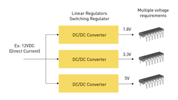
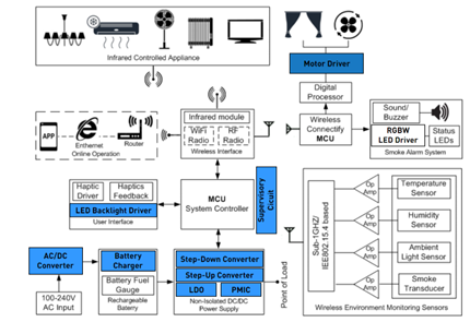
图1: DC/DC变换器
DC/DC 变换器是很多电子系统中必不可少的组件,它负责将一定水平的直流 (DC) 电压转换为其他水平的电压。这种变换器可以调节并稳定各种电子系统中的电压,确保组件获得恰当的指定电压,从而实现最佳性能以及安全性(见图 1)。在电源、电池充电器、电动汽车和可再生能源系统等多种应用中,DC/DC 变换器均发挥着关键的作用。本文将讨论 DC/DC 变换器及其常见类型、基本工作原理、关键参数和实际应用。
DC/DC变换器的类型
DC/DC 变换器主要有两种类型:线性变换器和开关变换器。
线性稳压器
线性稳压器采用线性元件,例如工作在线性区的电阻或晶体管,通过改变转换路径中的电阻来维持恒定的输出电压。其调节电路持续改变电阻,调节分压网络以维持恒定的输出电压,如图2所示。
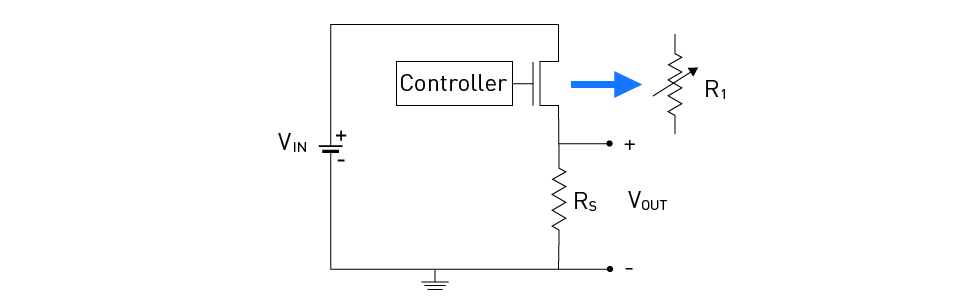
图2:基本线性稳压器电路
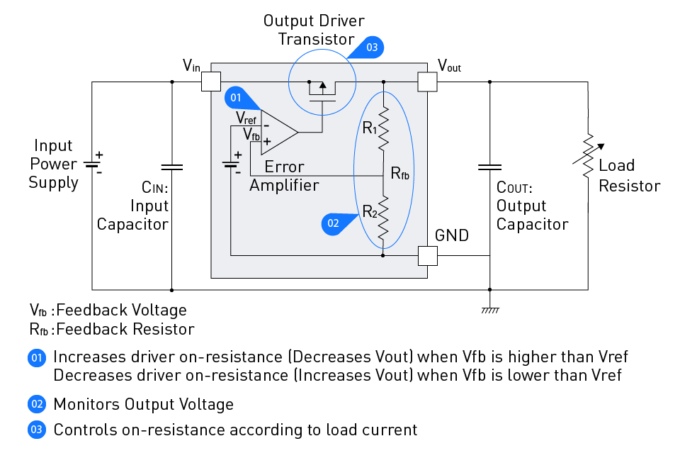
图 3:带反馈的线性稳压器功能
在典型的线性稳压器中,反馈信号通常由一个简单的误差放大器处理,来确保输出稳定的电压(如图3所示)。它通过电阻分压器对输出电压(Vo)进行降压得到反馈电压,并与参考电压(Vref)进行比较,再通过调节输出驱动晶体管的导通程度实现输出电压的调节。Vo的表达式如下:
$$ Vo = Vref \times \frac{R1 + R2}{R2} $$线性稳压器只能输出低于输入电压的电压。而且在此过程中,输入电压与调节后输出电压之间的电压差(称为压差电压)会导致能量损失。如图4所示的3.3V线性稳压器,0.5W的输入功率中有0.17W在电压转换过程中被耗散 。
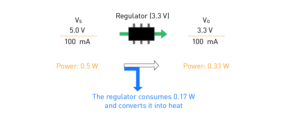
图4:线性调节存在能源浪费
低压差 ( LDO ) 稳压器是线性稳压器的一种变体,它可以在稳压过程中产生较小的压降。LDO 中的传输元件通常用 PMOS 或 NMOS FET 实现,根据负载状态,它们产生的压差可低至 30 mV 至 500 mV。


线性稳压器的关键参数如下:
输入电压范围:可施加于输入端的电压范围。输入电压范围(或最大额定值)必须保证产品的正常运行或满足规格要求。
输出电压范围:从稳压器处能够可靠获得的输出电压范围。
输出精度:调节过程中可能产生的误差程度,以+/-%表示。
输出电流:从稳压器输出端能够可靠获得的电流。
压差电压:调节输出所需的输入和输出之间的电压差,也被称为损耗电压或输入输出电压差。如果压差太小,稳压器将无法正常工作。
瞬态响应特性:当负载电流发生快速变化(例如大功率负载唤醒)时,输出电压波动至稳定的速度。瞬态响应特性可以通过绘制经验数据来验证。输出电容和IC性能都对瞬态响应特性有影响。
纹波抑制比:输入电压中包含的纹波在输出电压中被抑制的百分比。通常以dB表示,有时也用PSRR (电源电压纹波抑制比)或输入电压纹波抑制比来表示。需要注意的是,它取决于纹波的频率。
静态电流:当外部负载电流为零时,为稳压器内部电路供电所需的电流。它包括过流和过温检测电路、误差放大器、输出分压器和带隙基准所需的工作电流。输入电压、温度和拓扑结构都会影响静态电流。
负载调整率:给定负载变化时的输出电压变化。变化范围通常定义为从空载到满载。
线性调整率:给定输入电压变化时输出电压的变化。通常需考虑整个输入电压范围。
额定温度:这是稳压器在满载情况下不得超过的最高温度。超过此安全极限可能会导致稳压器过热甚至损坏。
开关DC/DC变换器
开关变换器采用高速电子开关交替连接和断开储能元件(包括电感和电容)的输入电压,并对这个过程中产生的脉动输出电压进行滤波和平滑处理,从而产生稳定的输出电压。开关变换器效率较高,可以处理更宽的输入和输出电压范围,但与线性变换器相比,它们更复杂,产生的噪声也较大。
常见的开关 DC/DC 变换器类型包括:
1. 降压(Buck/step-down)变换器
降压变换器可以将输入电压从较高的电压水平转换成较低的输出电压水平。图5展示了一个基本的降压变换器电路图。
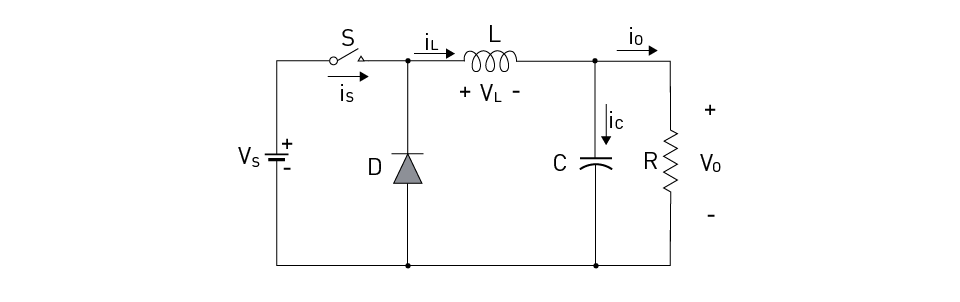
图5: 降压变换器电路
降压变换器的开关 (S) 工作在高频。当 S 导通时,输入电压源 (Vs) 提供电流 (is),分别以电流 iL和ic为电感 (L) 和电容 (C) 充电。负载 (R) 由反向偏置的 D 供电,C则调节输出电压 (Vo)。相反,当 S 关断时,二极管变为正向偏置,为iL提供负载电流 (Io) 路径。在这种变换器中,电感和电容需要合理设计,才能最大限度地降低输出中的纹波电流和电压。
2. 升压(Boost/step-up)变换器
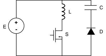
升压变换器可以将输入电压从较低水平转换为较高水平。基本的升压变换器电路如图6所示。
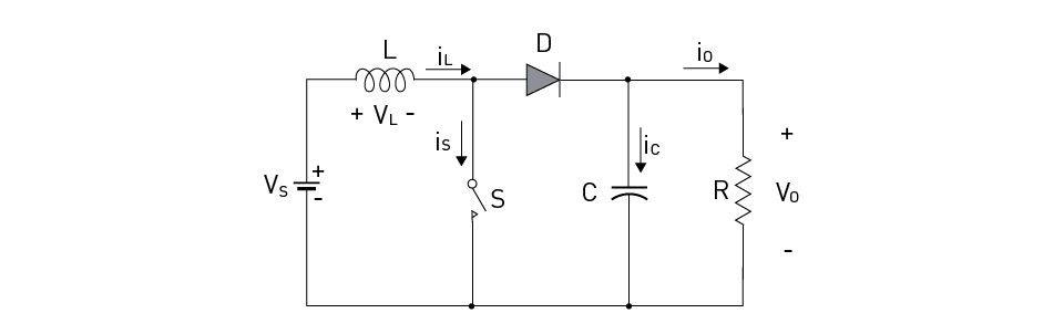
图6:升压变换器电路
当开关 S 导通时,源极 (Vs) 为电感 (L) 充电,电流 ( iL ) 流经开关 (is),剩余电路短路。当 S 断开时,输入电流将流经 L、二极管 (D)、电容 (C) 和负载 (R)。流经 C 和 R 的电流分别以ic和 Io 表示。电感 L 中存储的能量将被传输至负载;直到下一个周期,当S 重新导通时,电感电流才会减小。
3. 升降压(Buck-Boost或step-up/down)变换器
顾名思义,升降压变换器结合了降压变换器的降压功能和升压变换器的升压功能。由于其输出极性与输入极性相反,这类变换器也称为反相稳压器。图 7显示了一个基本的升降压变换器电路图。
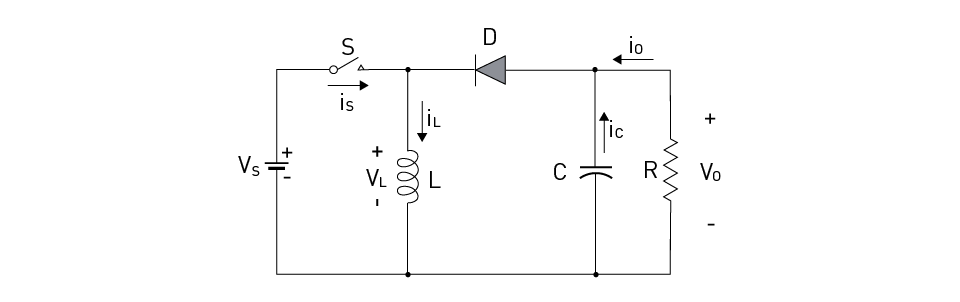
图7:升降压变换器电路
当开关 (S) 导通时,输入电压源 (Vs) 为电感 (L) 提供输入电流。当开关 S 断开负载 (R) 时,输出电容 (C) 和二极管 (D) 均接收流经电感 L 的电流;直到开关 S 在下一个周期重新导通,存储在电感 L 中的能量才会传递给负载,电感电流减小。通过工作占空比,可以控制变换器是在降压模式下运行,还是在升压模式下运行。.
其他变体
以上内容仅介绍了基本的开关DC/DC变换器拓扑,实际上还有其他几种可用的拓扑,例如Cuk、 Sepic和Zeta变换器。而且,上述DC/DC变换器类型在输入和输出之间没有提供任何电气隔离。有些电路拓扑是可以实现隔离的,例如正激式、推挽式、反激式变换器等变压器变体。此外,还有允许电流双向流动的双向变换器,电流可以在其输入源和负载之间双向流动。
开关DC/DC变换器相关原理与方法
电压调节方法
DC/DC 变换器的输出电压调节可以采用不同的调制方法,例如脉宽调制 ( PWM ) 或脉冲频率调制 (PFM)。在PWM中,占空比会改变,但频率保持不变。其开关损耗会降低效率,因为即使在轻载条件下,频率仍是恒定的。但是,通过设定频率可以更容易地过滤噪声。在 PFM 中,导通(或关断)时间固定,而关断(或导通)时间可以修改。在较低频率下运行可减少开关损耗。但PFM 中的噪声过滤比较困难,因为频率未知,这导致可闻频带中可能出现噪声。图 8 描述了PWM和 PFM 技术之间的差异。
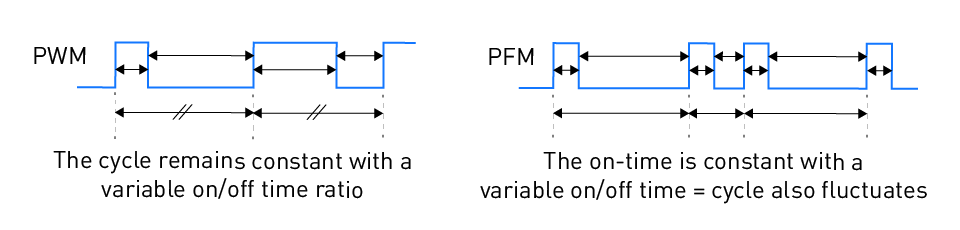
图8: PWM与PFM的差异
非同步/同步变换器
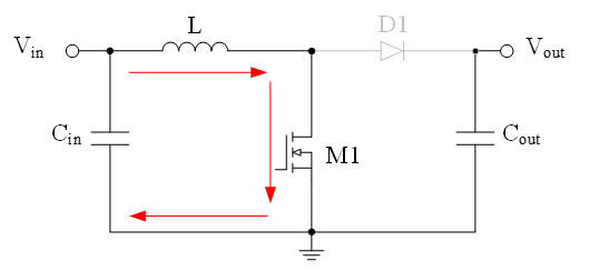
非同步变换器是采用二极管作为整流元件的开关稳压器。图9显示了一个非同步降压变换器电路。
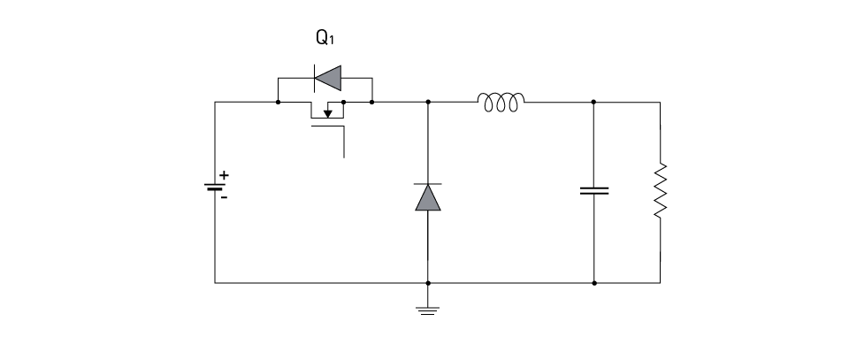
图9:非同步降压变换器电路
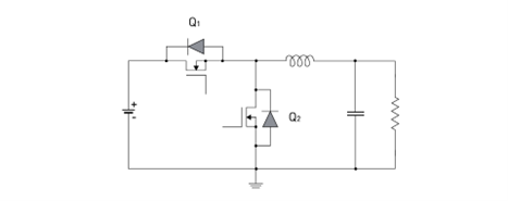
图10:同步降压变换器电路
值得注意的是,通过将二极管整流元件换为晶体管,可以将其他拓扑结构(例如升降压、升压、反激式等)构建为同步变换器。这样做的优势在于避免了二极管正向压降导致的效率下降。在低输出电压电路中这个优势尤其显著。但效率的提高是以更复杂的开关驱动电路为代价的。用户必须非常谨慎地设计,通过必要的措施防止同时打开两个开关,从而导致输入电压源短路;在PWM驱动信号中添加死区时间(也称为消隐时间)可以避免这种情况。同步变换器在最佳条件下的效率通常较高(约95%),而非同步变换器在最佳条件下的效率则较低(约80%)。
控制方法
在变化的负载和输入电压条件下调节DC/DC 变换器的输出电压需要一定的控制方法。DC/DC 变换器主要采用两种控制技术:电压模式控制和电流模式控制。
1. 电压模式控制
电压模式控制是最基本的控制技术,它使用反馈回路,但仅返回输出电压,如图11所示。其PWM发生器将三角波与差分电压进行比较;差分电压由误差放大器比较输出电压和参考电压获得。输出电压是由PWM信号的脉冲宽度控制的。
这种方法的优点在于非常简单,因为它采用的反馈回路只用到了电压而且具有较高的噪声容限。不过,相位补偿电路的复杂性和繁琐的设计方法可能成为其潜在的缺点。
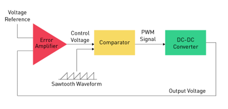
图11:电压模式控制
电流模式控制是电压模式控制的一种变体,它用电路中的电感电流或上管 MOSFET 的导通电阻取代了电压模式控制中使用的三角波形,如图 12 所示。电流模式有两种不同类型的反馈回路:电压回路和电流回路,因此这种控制方法也是相当复杂的。
电流模式控制的优点包括:大大简化了相位补偿电路的设计,且具有比电压模式更快的负载瞬态响应。但由于电流采样灵敏度极高,因此存在噪声耐受性低的缺点。不过,一些新设计已经解决了这个问题,因为电流检测元件被集成到了IC中。
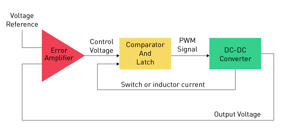
图12:电流模式控制
滞后(或称 Bang-Bang)控制则是另一种 DC-DC 变换器控制策略,也是最容易用硬件实现的方法。这种方法不使用误差放大器,而是利用比较器直接检查输出电压。当比较器确定输出电压达到或低于预定阈值时,将直接激活或停用开关。由于比较器施加直接控制且无需相位补偿,因此这种方法具有超快瞬态响应。不过,滞后控制会导致半导体开关的工作频率发生变化,这是它的缺点。
2. 软开关技术
上述基本DC-DC变换器都采用了硬开关方法。它也可以采用一种称为软开关方法的先进技术。软开关方法可以消除一个或多个电源开关的导通或关断损耗。它与硬开关不同,硬开关的电源开关导通和关断均在大电流和高电压下进行。
开关DC/DC变换器的重要参数如下:
- 效率:输出功率与输入功率的比率,表示变换器传输输入功率的效率。
- 负载和线性调整率:在变化的负载和输入电压条件下维持稳定输出电压的能力。
- 瞬态响应:变换器响应负载或输入电压突变的能力。
- 额定电压:DC-DC 变换器转换电压的上限或下限。
- 额定电流:DC-DC变换器能够安全提供给负载的最大电流量。变换器能够提供的电流可能更大,但超过额定电流可能导致过热并发生故障。
- 额定温度: DC-DC 变换器在满载下运行的最高温度。如果超过此安全限值,变换器可能会过热并损坏,或者出于安全考虑而关闭。
- 纹波电压:稳压器的输入/输出电压中出现的纹波。必须确保稳压器的电压纹波额定值符合要求。
MPS 提供了强大的 DC/DC 设计工具,可根据需求完成电源变换器的设计。
用户通过该工具可以分析各项设计性能,包括稳态、负载瞬态、环路分析、效率等。点击 此处访问在线设计师工具.
表 1 对线性和开关 DC/DC 变换器的显著特点进行了比较。
表1:线性和开关DC/DC变换器的比较
| 线性稳压器 | 开关稳压器 | ||||
|
降压 升压 升降压 反向 |
可实现 不可实现 不可实现 不可实现 |
可实现 可实现 可实现 可实现 |
|||
| 效率 |
VO / VIN 大多较低 |
约 95% 通常较高 |
|||
| 输出功率 |
一般为几瓦, 具体取决于散热设计 |
可产生高功率 | |||
| 噪声 | 低 | 有开关噪声 | |||
| 设计 | 简单 | 复杂 | |||
| BOM | 低 | 高 | |||
| 成本 | 低 | 相对较高 | |||
应用
DC/DC 变换器的应用非常广泛,涵盖了汽车、家用电子产品、手机、智能手表、机器人等。它们可以为设备电路提供最佳电压水平。用户可根据具体需求在线性变换器和开关变换器之间进行选择。有些情况下,这些变换器可以串联使用。例如,为了最大限度地降低开关 DC/DC 变换器的输出纹波,可以使用线性稳压器进一步稳压。
结语
DC/DC 变换器在众多电子系统中发挥着关键的作用,它提供了稳定的电压水平,确保了底层电路的最佳性能和安全性。本文介绍了两种基本类型的变换器:线性变换器和开关变换器,内容涵盖了其工作原理、重要设计参数、实际应用,以及二者的差异。
_______________________
您感兴趣吗? 点击订阅,我们将每月为您发送最具价值的资讯!
技术论坛
 Latest activity 6 months ago
 11 回复
Latest activity 5 months ago
24 回复
Latest activity 5 months ago
17 回复
11 回复
Latest activity 5 months ago
24 回复
Latest activity 5 months ago
17 回复
直接登录
创建新帐号