The processing or modification of a signal to get it ready for further processing steps is called "signal conditioning."
Amplification
A lot of sensors, particularly passive ones, give off weak output signals. These signals can range in magnitude from picoamperes (pA) to microvolts (µV). Several orders of magnitude greater input signals are needed for standard electronic processors like frequency modulators and ADCs.
That's why it's often necessary to amplify the sensor output signals significantly. Amplification guarantees that the output signal from a sensor is strong enough to be read, processed, or shown by other systems or devices.
Types of Amplifiers
Operational Amplifiers (Op-Amps): These are adaptable components that have a wide range of applications, from simple voltage followers to intricate integrative and differential circuits. Op-Amps, which have a low output impedance and a high input impedance, are essential components of contemporary electronics and play a key role in signal conditioning.
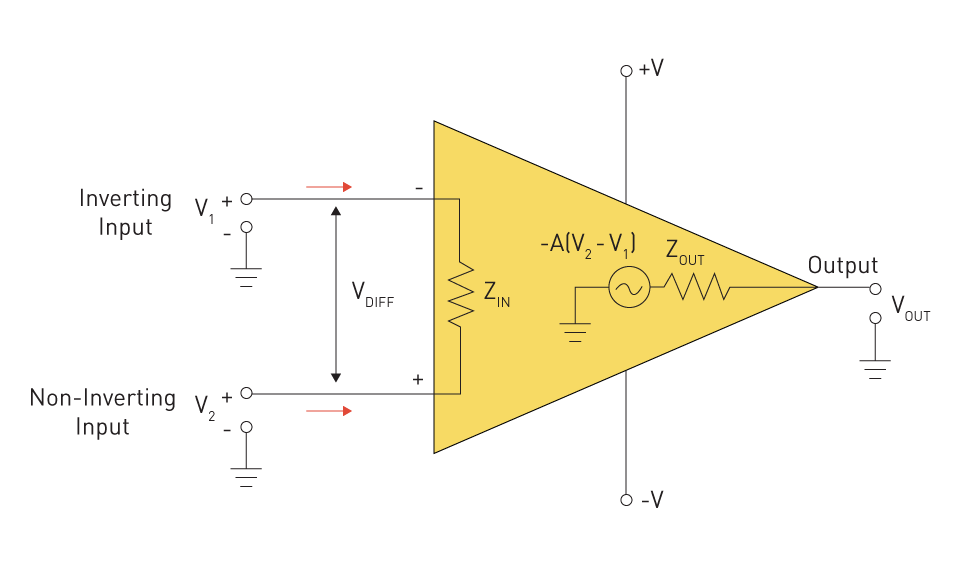
Figure 1: Operational Amplifier
Instrumentation Amplifiers: Instrumentation amplifiers offer high input impedance differential amplification specifically suited for sensor signal conditioning applications. Since they are designed to amplify small differential signals in the presence of huge common-mode voltages, they are especially useful in situations where sensor signals may be sent over noisy environments.
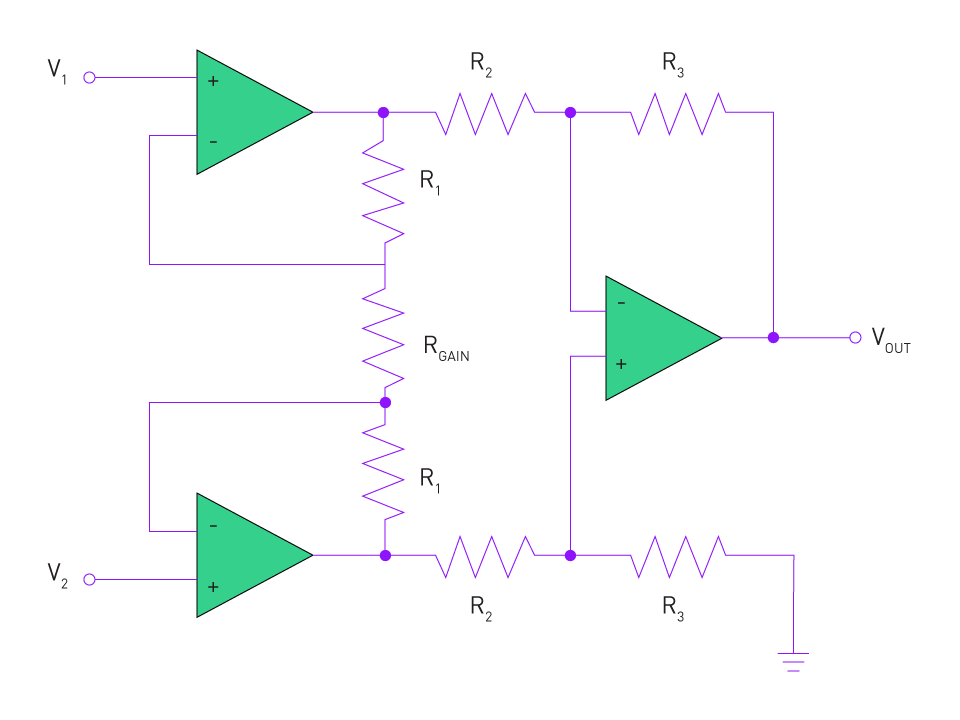
Figure 2: Instrumentation Amplifier
Gain Considerations and Noise Implications
Gain: The amplifier's gain controls the amplification factor, or the number of times the input signal is amplified. Although it would be tempting to boost a signal as much as possible, if the output voltage is higher than the amplifier's supply voltage, the amplifier could become saturated. It's critical to adjust the gain in accordance with the supply voltage and the anticipated input range.
Noise: Every amplifier adds noise to a signal to some degree. This noise may also be amplified at high levels of amplification, potentially interfering with the signal of interest. When developing signal conditioning circuits, it is imperative to take into account the amplifier's signal-to-noise ratio (SNR) and noise figure.
Importance of Amplification in Sensor Interfacing
When it comes to sensor interfaces, amplification has two functions.
Matching Voltage Levels: First, a lot of sensors generate extremely small output signals, which require amplification in order to meet the input specifications of devices that come after them, like analog-to-digital converters (ADCs).
Improving SNR: The overall Signal-to-Noise Ratio can be raised by amplifying the output signal from the sensor, which enables more precise and noise-free measurements.
To sum up, amplification is essential to signal conditioning since it makes sure that the sensor's output is calibrated and tailored for additional processing or interpretation. To get accurate and trustworthy sensor measurements, careful consideration of amplifier type, gain settings, and noise consequences is necessary.
Filtering
Filtering has a significant part in the field of signal conditioning. Its main job is to attenuate or remove unwanted components—mostly noise—while allowing desired ones to flow through by shaping the frequency content of the signal. The accuracy and dependability of sensor outputs can be greatly improved by a well-designed filter.
Importance of Noise Reduction
There are several possible sources of noise: intrinsic noise in the sensor, device flaws, temperature variations, and ambient electromagnetic interference. Whatever the cause, noise can obscure the true output of a sensor, making it challenging to get precise measurements. It's critical to eliminate or minimize noise:
Enhancing Signal Quality: Enhancing the signal-to-noise ratio (SNR) guarantees that the recovered data accurately depicts the phenomenon being monitored and enables more precise measurements.
Preventing Aliasing in Digital Systems: Aliasing is a phenomenon in digital systems where high-frequency material seems to be lower frequency due to sampling at a frequency that is not high enough to catch the highest frequency in the signal. Ensuring that only pertinent frequency content reaches the sampling stage is made possible by proper filtering.
Types of Filters
Low-Pass Filter: Attenuates frequencies higher than the cutoff frequency and permits signals with a frequency lower than the cutoff frequency to pass through. The removal of high-frequency noise is a common usage for it.
High-Pass Filter: This type of filter attenuates signals below a specific threshold while permitting high-frequency signals to pass, in contrast to the low-pass filter. It can be applied to a signal to eliminate undesirable slow-varying components.
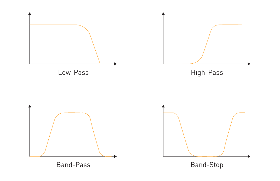
Figure 3: Types of Filters
Band-Pass Filter: This kind attenuates signals outside of a specific frequency range while allowing signals inside the band to flow. beneficial for separating out a specific interest frequency band.
Notch Filter (or Band-Stop Filter): It is extremely efficient at eliminating interference or noise at a specified frequency, such as power line noise at 50/60 Hz, because it is made to attenuate a particular narrow band of frequencies.
Analog vs. Digital Filtering Techniques
Analog Filtering: Implemented with the use of active components like operational amplifiers or passive like resistors, capacitors, and inductors. Due to their rapid reaction, analog filters are advantageous in real-time applications processing continuous-time signals. However, aging and component tolerances may have an impact on their performance.
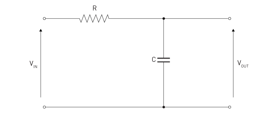
Figure 4: Analog Low-Pass Filter
Digital Filtering: Functions with discrete-time signals, frequently following an analog-to-digital conversion step. Algorithms are used to create digital filters, which are then implemented in microcontrollers or digital signal processors. Because software parameters can be altered to vary their qualities, they offer flexibility. They are able to produce precise filter shapes and extremely sharp cutoffs, which could be difficult in the analog domain. However, because of the complexity of the filter, there may be a computational delay and the need to digitize the signal.
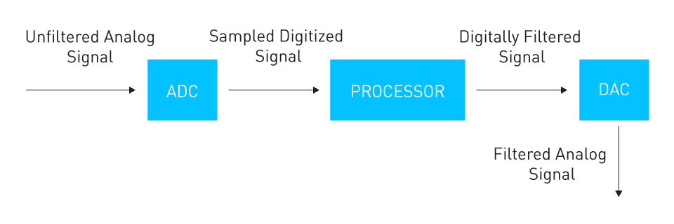
Figure 5: Digital Filtering
An essential instrument in signal conditioning is filtering. Whether one uses digital or analog methods, the objective is always the same: to identify the real signal among the noise so that sensor data may be interpreted with accuracy and dependability.
Analog-to-Digital Conversion (ADC)
In modern electronics, the shift from the analog to the digital domain is crucial, particularly in the sensor space. This conversion is generally carried out by an apparatus known as the Analog-to-Digital Converter (ADC). An ADC efficiently converts an analog voltage to a digital value, which makes it easier to handle or store the sensor's data digitally later on.
Principles of Quantization and Sampling
Sampling: At discrete time intervals, the continuous-time analog signal is first sampled. The Nyquist-Shannon sampling theorem states that in order to avoid aliasing, the sampling rate, often represented by the symbol fs, must be at least twice the highest frequency in the signal.
Quantization: Every sample has a finite digital value after it has been sampled. The method generates an inaccuracy known as quantization error by nature because there are only a finite number of digital levels (determined by the resolution of the ADC). This is the discrepancy between an analog value's closest digital equivalent and its real value.
Encoding: Encoding is the next phase in the analog-to-digital conversion process, which comes after the analog signal has been sampled and quantized. This is how a binary code representing each quantized value is created. Combinations of 0s and 1s are utilized in binary encoding, and the resolution of the encoding is determined by the number of bits employed in this representation. For example, you may represent 256 (28) different quantization levels using 8 bits. Every quantized sample has its own binary code assigned to it.
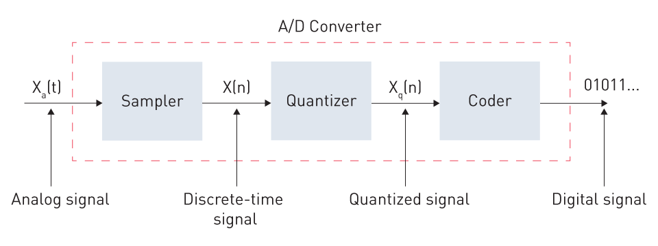
Figure 6: Basic Components of an Analog-to-Digital Converter
Different Types of ADCs
Successive Approximation ADC: Among the most popular ADC types is this one. It employs a sequential approximation register (SAR) in conjunction with a comparator to converge, much to a binary search, on the value of the input signal. It is renowned for striking a balance between power efficiency and speed.
Delta-Sigma (ΔΣ) ADC: ΔΣ ADCs are mostly utilized in high-resolution applications such as audio processing. They employ noise shaping techniques to exclude quantization noise from the intended frequency region and oversample the input signal. Although usually at lower sampling rates, this yields high-resolution outputs.
Flash ADC (Parallel ADC): The quickest kind of ADCs are flash ones, which can convert an analog input to a digital output in a single step. To ascertain the digital value quickly, they employ a variety of comparators. However, the complexity and power they require to achieve their high speed have increased.
Factors Affecting ADC Choice
Resolution: Indicates how many distinct levels the ADC is capable of producing. Finer granularity is possible with a greater resolution (more bits), but this usually comes at the price of conversion times or higher power usage.
Speed (Sampling Rate): Various sample rates are needed for various purposes. High-frequency radio communications may require rates in the multi-megahertz or even gigahertz range, whereas audio processing may require rates in the tens of kilohertz range.
Power Consumption: For gadgets that run on batteries or are portable, power efficiency is critical. Certain ADCs are made to run in low-power modes or to dynamically change their power in response to performance demands.
Accuracy and Linearity: In precision applications, total accuracy—which takes into consideration all possible flaws, including offset, gain, and non-linearity—can be just as important as resolution.
The process of converting analog signals to digital signals is the starting point for digital signal processing and is essential to contemporary electronics. Selecting the appropriate ADC necessitates taking into account the particular demands of the application and comprehending the compromises between resolution, speed, and power.
Linearization
The intrinsic non-linear response of some sensors is one of the complex problems in the field of signal processing and sensor interface. The remedial procedure known as "linearization" converts this non-linear output into a linear one, making it easier to process and comprehend data in the future.
Why Some Sensor Outputs Need Linearization
By definition, the output of many sensors is not linear over their whole measurement range. A non-linear relationship between magnetic field strength and output voltage may be seen in some magnetic field sensors, as well as in thermistors, whose resistance changes non-linearly with temperature. Direct readings might be deceptive or difficult to understand when a sensor produces non-linear output. Linearizing the output of the sensor becomes essential for precise measurement and for utilizing its full potential.
Techniques for Linearization
Electronic Circuits: To linearize sensor outputs, hardware solutions frequently use different circuit architectures.
Operational Amplifiers (Op-Amps): The output can be efficiently linearized by configuring op-amp configurations to offer the inverse of the non-linearity of the sensor. Sensors like as thermistors are frequently used with this technique.
Compensating Networks: These circuits, which are frequently composed of capacitors, resistors, and occasionally inductors, are intended to respond in a way that offsets the non-linear behavior of the sensor.
Software Methods: Software-based linearization has grown in popularity as microcontrollers and digital systems are integrated into sensor interfaces more and more frequently.
Lookup Tables: The non-linear sensor output and a linearized value are correlated using a predetermined table. The system looks for the matching linear value in this table when the sensor gives a reading.
Polynomial Correction: The non-linear behavior of the sensor is represented by mathematical models, which are frequently in the form of polynomial equations. Subsequently, the output of the sensor is linearized and corrected in real time using this model.
Curve Fitting Algorithms: The best-fit curve for the sensor's output can be found using sophisticated algorithms. After it is established, further readings can be linearized using this curve.
In summary, the process of linearization is essential to guaranteeing consistent, dependable, and easily interpreted sensor outputs. It is a crucial component of contemporary sensor interface, providing the groundwork for precise data collection and analysis, regardless of how it is accomplished through electronic circuits or software algorithms.
Compensation Techniques
The process of signal conditioning involves more than just format conversion and amplitude adjustment. Additionally, it deals with the numerous errors and discrepancies that come with sensor readings. In order to guarantee that the conditioned signal accurately depicts the observed phenomenon, compensation approaches work to address these flaws.
Addressing Offset and Drift
Offset: An example of a systemic error is offset error, in which even in the case of zero input, the output of a sensor is continuously higher or lower than the real value by a predetermined amount. When no pressure is applied, for example, a pressure sensor could nonetheless generate a non-zero result. The offset value must be subtracted from the sensor's output in order to account for this mistake.
Methods of Addressing Offset: This can be accomplished with software methods where the detected offset is removed programmatically from each reading, or with hardware methods such as a summing amplifier where a negative offset voltage is injected to counteract the inaccuracy.
Drift: When the input to a sensor is constant, drift is the slow, steady change in the sensor's output. Ageing components, temperature swings, and long-term environmental changes are some of the possible causes.
Methods of Addressing Drift: One of the popular fixes is periodic recalibration. By tracking measurements over time and implementing the appropriate modifications, such as modifying the sensor's operating settings or performing post-measurement corrections, automated systems can be incorporated to identify drift.
Temperature Compensation for Maintaining Sensor Accuracy
Nearly all sensors exhibit some degree of sensitivity to temperature changes. Temperature variations can cause inaccuracies in the sensor's materials or in the electronics that analyze the readings.
Active Temperature Compensation: There are sensors that have an additional temperature sensor built in. The primary sensor's readings can be instantly altered by continuously monitoring the temperature because the sensor's temperature characteristics are known. Sensors that operate in situations with frequent temperature variations will find this strategy especially helpful.
Lookup Tables and Algorithms: Lookup tables or correction algorithms can be used for sensors that have well-defined temperature characteristics. To ensure accuracy throughout the sensor's complete operating temperature range, a correction factor is applied to the output based on the current temperature.
Material Selection and Design: Active compensation strategies may not always be necessary when choosing materials with low temperature coefficients or when building the sensor to decrease temperature sensitivity.
Understanding a sensor's subtleties and flaws and applying a variety of strategies to neutralize or reduce their effects is the foundation of compensation approaches. Getting the most accurate depiction of the measured parameter is the ultimate goal, and it is always evident.


直接登录
创建新帐号