Principles of Active Filtering
Active filters are used for harmonic elimination in power systems. Unlike passive filters that use reactive power components (capacitors and inductors) to create a path for harmonic currents, active filters work by injecting currents that are equal in magnitude but opposite in phase to the harmonic currents present in the system.
The principle of active filtering can be understood by considering a simple case of a single-phase system. If a nonlinear load generates a harmonic current, this current will distort the voltage waveform in the power system, leading to poor power quality. An active filter connected to this system measures the load current, calculates the harmonic components, and then generates a compensation current that is the exact negative of the harmonic current. When this compensation current is injected into the system, it cancels out the harmonic current, resulting in a sinusoidal total current.
Active filters are primarily controlled by power electronic devices such as Insulated Gate Bipolar Transistors (IGBTs) or MOSFETs. These devices switch on and off at high speeds, allowing the filter to respond quickly to changes in the load current and maintain effective harmonic compensation.
Active filters have several advantages over passive filters. They can eliminate multiple harmonics simultaneously and adapt to changes in the power system frequency and the harmonic spectrum. Furthermore, they do not create resonance problems in the power system, which can occur with passive filters.
Types of Active Filters
Active filters for harmonic mitigation can be broadly categorized into three types: shunt active filters, series active filters, and hybrid active filters.
Shunt Active Filters
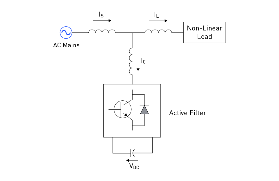
Shunt active filters are connected in parallel to the load. These filters estimate the harmonic current from the load and generate a compensating current that cancels out the harmonic component. Shunt active filters are especially effective for mitigating current harmonics and can compensate for unbalanced and reactive loads. They are primarily used to improve the power factor, balance the load, and eliminate harmonics. The shunt active power filter topology is shown in Figure 4.

Figure 4: Shunt Active Filter
Series Active Filters
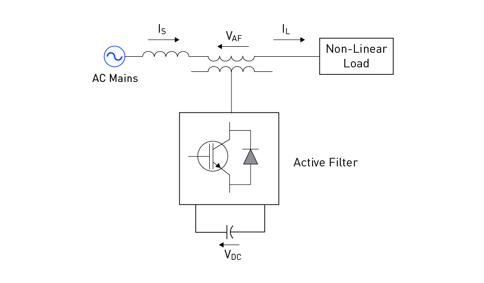
Series active filters, as their name suggests, are connected in series to the power system. They work by injecting voltage that cancels out the harmonic voltage in the system, thus ensuring that the load receives sinusoidal voltage. Unlike shunt active filters, which primarily address current harmonics, series active filters effectively mitigate voltage harmonics. They are commonly used to suppress voltage flicker, regulate the terminal voltage, and isolate the load from the supply. The series active power filter topology is shown in Figure 5.

Figure 5: Series Active Filter
Hybrid Active Filters
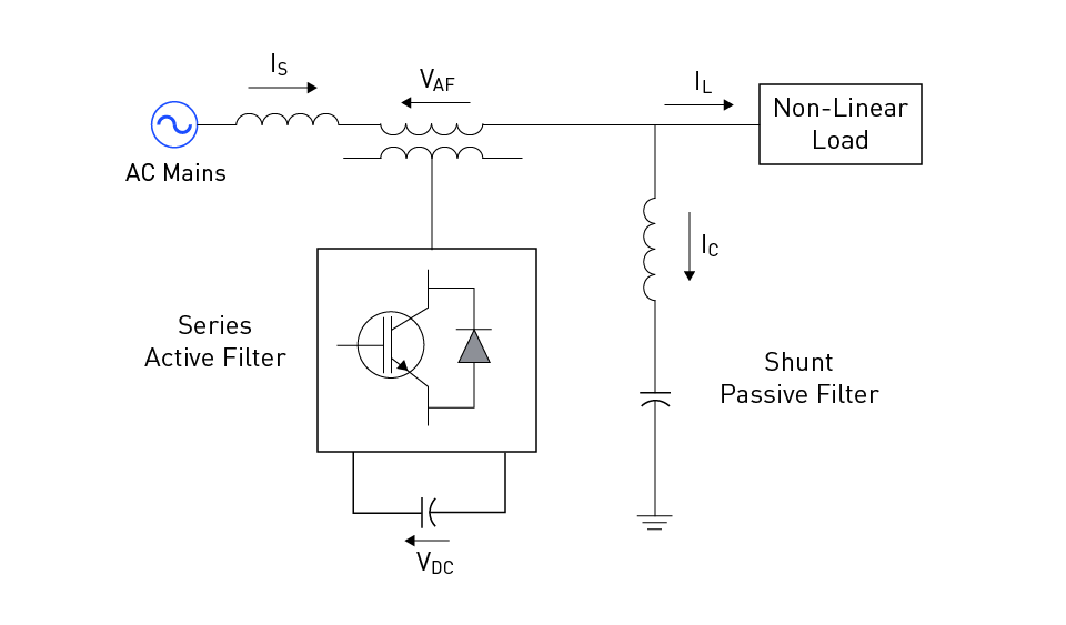
Hybrid active filters are a combination of both shunt and series filters, usually incorporating a passive filter. This configuration allows for the simultaneous mitigation of both current and voltage harmonics. The active part of the filter handles the higher-order, variable-frequency harmonics, while the passive part handles the fixed-frequency, lower-order harmonics. Hybrid active filters exploit the advantages of both series and shunt filters while minimizing their disadvantages. The hybrid active power filter topology is shown in Figure 6.

Figure 6: Hybrid Active Filter
Control Strategies for Active Filters
Two of the most common control strategies employed in active filters are the Synchronous Reference Frame (SRF) method and the Instantaneous Reactive Power Theory (IRPT). These methodologies differ in their complexity, calculation speed, and suitability for various scenarios.
Synchronous Reference Frame Method
The Synchronous Reference Frame (SRF) method, also known as the dq0 transformation, is a widely used control strategy for active filters. The core concept behind this method is to transform the three-phase voltages and currents from the time domain (ABC) into the synchronous dq0 frame, where the signal analysis becomes more straightforward.
In the synchronous frame, the currents and voltages are represented as DC quantities, and the harmonic components appear as AC signals. The control algorithm estimates the harmonic components by filtering out the DC part of the signal and then generates the compensating current to eliminate these harmonics. The SRF method is highly effective in extracting harmonic components, even in unbalanced and variable frequency conditions.
Instantaneous Reactive Power Theory
Instantaneous Reactive Power Theory (IRPT), also known as the p-q theory, is another control strategy used in active filters. This method calculates the active (p) and reactive (q) powers in real time and uses these quantities to determine the reference compensating currents.
The IRPT is designed for instantaneous compensation, making it suitable for non-sinusoidal, unbalanced, and rapidly varying loads. Unlike the SRF method, which requires transformation to a synchronous frame, the IRPT works directly in the time domain. This feature makes the IRPT a computationally efficient method, especially valuable for real-time applications.
However, it's essential to note that the p-q theory assumes the source voltage is sinusoidal and balanced. If this assumption doesn't hold, the compensation performance may degrade.
Both SRF and IRPT are powerful tools for the control of active filters. The choice between these methodologies depends on the specific requirements of the power system, such as the nature of the load, the harmonic spectrum, and the computational resources available.
Design Considerations for Active Filters
Rating and Sizing of Active Filters
The rating and sizing of active filters are crucial considerations in their design process, and these are primarily determined based on the nature of the load and the harmonic spectrum present in the power system. The rating of an active filter is typically expressed in terms of its VA (volt-ampere) capacity, which defines the maximum apparent power that the filter can handle.
When sizing an active filter, it is essential to consider the fundamental frequency current and the harmonic currents the filter is expected to eliminate. The harmonic spectrum analysis of the load is typically conducted to assess the harmonic current levels at various frequencies. The active filter must be sized adequately to handle the peak harmonic current, ensuring effective harmonic compensation under all operating conditions.
Integration with Power Electronic Converters
In active filters, power electronic converters serve as the central component that interfaces the filter with the power system. The integration of active filters with power electronic converters entails several critical considerations.
Firstly, the choice of the power electronic converter topology impacts the performance of the active filter. Commonly used topologies include the Voltage Source Converter (VSC) and the Current Source Converter (CSC), each with advantages and specific applications. The VSC, for instance, is advantageous for shunt active filters, given its capability to generate the required compensation current irrespective of the load current.
Secondly, the control scheme for the power electronic converter is a crucial aspect of the active filter design. The control scheme determines how the converter responds to the compensation commands from the filter control algorithm. Common control strategies include the hysteresis control, PI control, and sliding mode control, each with distinct performance characteristics and implementation complexities.
Finally, the design of the power electronic converter should consider the system's power rating, operating voltage and frequency, and thermal management requirements. These factors define the specifications for the power electronic devices (IGBTs, MOSFETs, diodes, etc.) and other components (inductors, capacitors, heat sinks, etc.) used in the converter design.
Standards and Regulations for Power Quality and Harmonics
IEEE 519 Standard
IEEE 519 is a widely accepted standard that defines limits for harmonic current and voltage distortions in power systems. This standard applies to customers (power consumers) and utilities (power providers). The standard categorizes systems based on their bus voltage and stipulates harmonic distortion limits accordingly. Harmonic limits are given for individual harmonics and total harmonic distortion (THD), which measure the cumulative effect of all harmonic frequencies.
Compliance with the IEEE 519 standard is of utmost importance in designing active filters. The filters need to limit the harmonic distortion to levels within the IEEE 519 prescribed limits under all operating conditions. This necessitates detailed harmonic studies at the design stage to predict harmonic levels and appropriately size the filters.
IEC 61000 Standard
The IEC 61000 standard, set by the International Electrotechnical Commission, defines limits and guidelines for electromagnetic compatibility (EMC) in power systems, which includes harmonics and inter harmonics. This standard sets different equipment classes, each with its specific harmonic limits. It provides a comprehensive guide for assessing, mitigating, and limiting electromagnetic disturbances, including harmonics.
In the context of active filters, the IEC 61000 standard dictates how these systems should perform under various electromagnetic disturbances and the level of harmonics they should be able to manage. It is a crucial standard to consider when designing and implementing active filters.
Utility Requirements and Compliance
In addition to the above international standards, utilities often set their own requirements for power quality and harmonic levels, which are usually based on their power system's specific characteristics and operational requirements. These could be stricter than what's prescribed in the IEEE 519 and IEC 61000 standards, primarily to ensure the stability and reliability of their network.
Utilities require customers to comply with these requirements, failing which penalties may be imposed. Therefore, the active filter design must meet the international standards and the specific requirements set by the utility.
In summary, the standards and regulations are integral to the design and operation of active filters for harmonic elimination. They serve to establish a common ground for defining acceptable harmonic levels and ensure that all connected devices operate reliably without interfering with each other's operation.

直接登录
创建新帐号