Introduction and Principle of Operation
A flexible DC-DC converter architecture that combines the advantages of step-up (boost) and step-down (buck) converters is known as the "Ćuk converter." It bears the name of Dr. Slobodan uk, who developed the topology and first suggested it in the late 1970s. The Ćuk converter has a number of benefits over traditional converters, including the ability to handle a wide variety of input voltages, continuous input, and output currents, and reduced electromagnetic interference (EMI). These qualities make it a desirable option for a variety of power conversion applications, especially in systems where effective energy management and minimal electromagnetic interference (EMI) are essential.
The inductor-capacitor (LC) network is used to maintain energy transfer when switching between two states in the UK converter's operating principle. The ON state, in which the switch is closed, and the OFF state, in which the switch is open, are the two operating modes for the converter. In the ON state, the input inductor stores energy while the output capacitor powers the load, while the input inductor sends its stored energy to the output capacitor in the OFF state, continuing to power the load. The input and output currents are continuously smoothed by this energy transfer between the input inductor and output capacitor, which lowers the converter's overall ripple and EMI emission.
Circuit Topology and Key Components
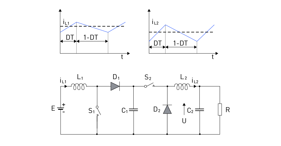
All previously described converter configurations have a common drawback, which is that the input current of the converter, the output current of the converter, or both are discontinuous. One way to make the input and output current continuous while preserving the function of both buck and boost converters is to connect these two converters in series, as shown in Figure 12. The transfer function of this new converter is equal to the product of the transfer functions of the series-connected converters:
$$U = E \cdot \frac{T}{t_{OFF}} \cdot \frac{t_{ON}}{T} = E \cdot \frac{t_{ON}}{t_{OFF}}$$In this configuration, synchronous switch control is adopted, which means that both switches are turned on during the tON period and both switches are turned off during the tOFF period.

Figure 12: Series connection of the boost and the buck converters
The main disadvantage of the previous converter configuration is the use of four switching elements (S1, S2, D1, and D2), which leads to increased losses and decreased efficiency. In addition, there is a large alternating component of the current in capacitor C1. Dr. Slobodan Ćuk proposed a converter configuration with the same properties but with a smaller number of switching elements (Figure 13), known as the Ćuk converter. For the analysis of the converter operation, it can be assumed that the capacitances of capacitors C1 and C2 are large enough to neglect the alternating component of the voltage across them.

Figure 13: The Ćuk converter circuit diagram
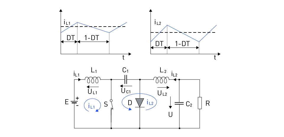
In this converter, during the tON interval (Figure 14), the switch S is turned on, inductor L1 is connected to the DC power source E, while the diode D is reverse biased with the voltage across capacitor C1. In steady-state, the average voltage across inductors is zero, so the average voltage across capacitor C1 is $$U_{C1} = U + E$$
Under the influence of voltage E, the current through inductor L1 linearly increases from the minimum to the maximum value. At the same time, inductor L2 is connected to a voltage that is equal to the difference between the load voltage and the voltage across capacitor C1, so its current also linearly increases from the minimum to the maximum value.

Figure 14: The Ćuk converter circuit diagram – interval tON
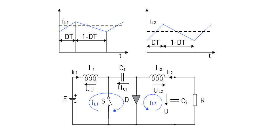
During the tOFF interval (Figure 15), when the switch S is turned off, the current through inductor L2 is closed through the diode D, connecting inductor L2 to the load voltage, so its current linearly decreases from the maximum to the minimum value. At the same time, inductor L1 is connected to a voltage that is equal to the difference between the voltage across capacitor C1 and the DC power source E, causing its current to decrease from the maximum to the minimum value.

Figure 15: The Ćuk converter circuit diagram – interval tOFF
In steady-state, the average voltage across the inductors is zero, so the average voltage across capacitor C1 is:
$$U_{C1}=U+E$$The change in the inductor current during a period T is proportional to the area of the voltage across the inductor:
$$u_L = L \frac{di_L}{dt} \Rightarrow \Delta I_L = \frac{1}{L} \int_0^T u_L dt$$In steady-state, the total change in the inductor current is zero because the average value of the voltage across the inductor is zero:
$$\Delta I_L |_{t_{ON}} = \frac{E}{L_1} \cdot T \cdot d = \Delta I_L |_{t_{OFF}} = \frac{U_{C1} - E}{L_1} \cdot T \cdot (1 - d)$$The previous equations yield:
$$U = \frac{d}{1 - d} \cdot E = E \cdot \frac{t_{ON}}{t_{OFF}}$$and this is the transfer function of the buck-boost converter.
The Ćuk converter consists of several key components arranged in a unique topology to enable its advantageous features, such as continuous input and output currents and reduced EMI. The primary components of the Ćuk converter include:
- Input source: The DC voltage source that provides the input power for the converter.
- Input inductor (L1): This inductor stores energy during the ON state and transfers it to the output during the OFF state.
- Output inductor (L2): This inductor smooths the output current, minimizing the ripple and contributing to the converter's continuous output current characteristic.
- Capacitor (C1): This capacitor facilitates energy transfer between the input and output inductors during the switching process.
- Output capacitor (C2): This capacitor filters and smooths the output voltage, providing a stable DC output to the load.
- Switch (S): Typically a MOSFET or IGBT, the switch controls the energy transfer between the input and output inductor by alternating between the ON and OFF states.
- Diode (D): This diode ensures that current flows in the correct direction during the switching process and prevents reverse current flow when the switch is in the OFF state.
The unique topology of the Ćuk converter features an LC network formed by the input inductor (L1), coupling capacitor (C1), and output inductor (L2). The input and output inductors are connected in series, and the coupling capacitor is connected between them. When the switch is closed (ON state), the input inductor stores energy and the output capacitor supplies power to the load. When the switch is opened (OFF state), the input inductor transfers its stored energy to the output capacitor through the coupling capacitor, and the output inductor smooths the output current.
Continuous and Discontinuous Conduction Modes
The Ćuk converter can operate in two different conduction modes: continuous conduction mode (CCM) and discontinuous conduction mode (DCM). The mode of operation depends on the converter's load, switching frequency, and the values of the inductors and capacitors in the circuit.
Continuous Conduction Mode (CCM): During the switching cycle, the current flowing through the input and output inductors never reaches zero. This mode of operation yields improved dynamic response, less EMI, and lower current ripple. To maintain the constant current flow, larger inductors and capacitors are needed. When the load is sufficiently high or the switching frequency is low enough, the converter runs in CCM.
Discontinuous Conduction Mode (DCM): During a portion of the switching cycle, the current flowing through the input and output inductors reaches zero. In comparison to CCM, this mode of operation has a greater current ripple, more EMI, and a slower dynamic response. Nevertheless, it permits the use of smaller inductors and capacitors, which may result in a more portable and portable converter design. When the load is minimal or the switching frequency is high enough, the converter runs in DCM.
Design Considerations and Calculations
Designing a Ćuk converter involves several critical considerations and calculations to ensure optimal performance and efficiency for the specific application. These considerations include selecting appropriate component values, calculating the duty cycle, and ensuring stability.
Component selection: The performance of the converter is greatly influenced by the choices of inductors, capacitors, and switches. Based on the intended output voltage, current, input voltage range, and switching frequency, designers must carefully choose these components. While capacitors should have low equivalent series resistance (ESR) and strong ripple current capability, inductors should have low core losses and low series resistance. The switch should have a low on-state resistance and quick switching times (usually a MOSFET).
Duty cycle calculation: The duty cycle, D, is the ratio of the switch's on-time to the total switching period. The duty cycle determines the relationship between input and output voltages in a Ćuk converter. The following formula expresses the relationship between input voltage (Vin), output voltage (Vout), and duty cycle:
$$V_{out} = -\frac{V_{in} \cdot D}{1 - D}$$Designers can use this formula to calculate the required duty cycle for a given input and output voltage.
Stability: A Ćuk converter has several energy storage components, therefore it can exhibit complicated dynamics, as a result, stability in the converter must be ensured. Over its full operating range, the converter's control loop should retain stability. To assess the converter's stability and create a control loop that takes that into account, designers can utilize methods like root locus analysis or Bode plots.
Efficiency: Designers should reduce conduction and switching losses to obtain high efficiency. To achieve this, low-loss components must be used, and the switching frequency needs to be optimized. A balance must be struck because raising the switching frequency might also result in larger switching losses.
Thermal management: Designers must consider the thermal performance of the Ćuk converter, as excessive heat can lead to component failure or decreased efficiency. Proper heat sinking, component selection, and layout can help manage thermal issues.
Efficiency and Losses
Efficiency is a crucial aspect of power converter design, as it directly affects power consumption, thermal performance, and component reliability. In a Ćuk converter, various factors contribute to efficiency and losses, which are essential to understand and minimize for optimal performance.
Conduction losses: Conduction losses occur when current flows through the inductors, capacitors, and switching devices in the Ćuk converter. The resistance of these components generates heat, which is dissipated as power loss. To minimize conduction losses, designers should select low-resistance components, such as low-ESR capacitors and low-resistance inductors.
Switching losses: Switching losses arise when the converter's switch transitions between its on and off states. During this transition period, both current and voltage across the switch are non-zero, leading to power dissipation. Switching losses can be reduced by selecting fast-switching devices (e.g., MOSFETs) and optimizing the switching frequency. However, increasing the switching frequency can also increase switching losses, so a balance must be struck.
Core losses: Magnetic core losses in the inductors result from the alternating magnetic fields generated during the converter's operation. These losses can be minimized by selecting inductor cores with low-core loss materials and optimizing the switching frequency to reduce the rate of change in the magnetic field.
Capacitor losses: Capacitors in the Ćuk converter experience losses due to their equivalent series resistance (ESR) and dielectric losses. Selecting capacitors with low ESR and low dielectric loss materials can help reduce these losses.
Control and auxiliary losses: Additional losses may arise from the control circuitry and auxiliary components that regulate the Ćuk converter's operation. Optimizing the control circuit's design and selecting efficient auxiliary components can minimize these losses.
By understanding and addressing these various sources of losses, designers can improve the overall efficiency of a Ćuk converter. High-efficiency results in reduced power consumption and helps manage thermal issues, extending the converter's reliability and lifespan.
Applications and Examples
Ćuk converters find applications in various fields where precise regulation, high efficiency, and low output ripple are essential. Some of these applications and examples are discussed below:
Power supplies: Ćuk converters are often used in power supplies for sensitive electronic equipment due to their low output ripple, low electromagnetic interference (EMI), and high efficiency. They can be found in devices like laptops, medical equipment, and instrumentation systems.
Renewable energy systems: In photovoltaic (PV) systems and wind energy systems, Ćuk converters can serve as maximum power point tracking (MPPT) converters to optimize the power extraction from the renewable energy source. They can also be employed in battery charging circuits for energy storage systems, ensuring efficient and stable charging performance.
LED lighting: Ćuk converters are suitable for LED lighting applications, providing constant current to the LEDs while maintaining high efficiency and low output ripple. This ensures stable brightness and prolonged LED lifespan, which is especially important in commercial and industrial lighting installations.
Automotive electronics: Due to their ability to step-up or step-down voltage, Ćuk converters are used in automotive electronics systems for tasks like regulating the voltage for various subsystems, such as infotainment, power windows, and climate control. Their high efficiency and low EMI characteristics make them well-suited for these noise-sensitive environments.
Telecommunications: In telecommunication systems, Ćuk converters can provide power to remote equipment with varying input voltages, ensuring stable operation and consistent performance. Additionally, their low output ripple helps minimize interference with sensitive communication signals.
Robotics and industrial control: Ćuk converters can be utilized in robotics and industrial control systems to supply stable and regulated power to actuators, sensors, and other components. Their high efficiency and low EMI characteristics contribute to the overall system reliability and performance.
These instances show the Ćuk converter's adaptability to a variety of applications. Its special mix of attributes, including high efficiency, minimal output ripple, and minimal EMI, make it a wise choice in a variety of power conversion settings. Engineers may efficiently use uk converters to fulfill the unique requirements of diverse applications by understanding their operating principles and design factors.


直接登录
创建新帐号