Phase Controlled Rectifier
Phase-controlled rectifiers are circuits used in power electronics that enable the conversion of AC voltage to DC voltage by regulating the firing angle of thyristors. Thyristors are semiconductor devices that can regulate the flow of current by using a gate signal. Phase-controlled rectifiers are employed in a variety of applications, including motor drives, heating and lighting control, battery chargers, and power supplies for electronic devices.
Single-phase controlled rectifiers are a category of phase-controlled rectifiers that employ a single thyristor to control current flow. Unlike diode rectifiers that only allow current to flow in one direction, single-phase controlled rectifiers allow current to be controlled in both directions. By regulating the firing angle of the thyristor, the output voltage and current can be managed, enabling power regulation to the load. Single-phase controlled rectifiers are widely used in AC motor speed control and battery chargers.
Single-Phase Controlled Rectifier
Single-phase controlled rectifiers, also known as phase-controlled rectifiers, play a crucial role in power electronics applications. These devices are used to convert alternating current (AC) to direct current (DC) with the ability to control the output voltage. This is achieved by adjusting the firing angle (or phase angle) of thyristors, which are semiconductor devices capable of switching large currents.
Half-Wave Controlled Rectifier
A half-wave controlled rectifier utilizes a single thyristor that is connected in series with the load. Once triggered at a specific firing angle during the positive half-cycle of the input AC supply, the thyristor begins to conduct, and the output voltage waveform is determined by the firing angle and the input AC voltage amplitude. By adjusting the firing angle, the average output voltage can be controlled, which affects the amount of power delivered to the load. However, half-wave controlled rectifiers have the disadvantage of using only half of the input AC waveform, resulting in high harmonic distortion and poor power factor.

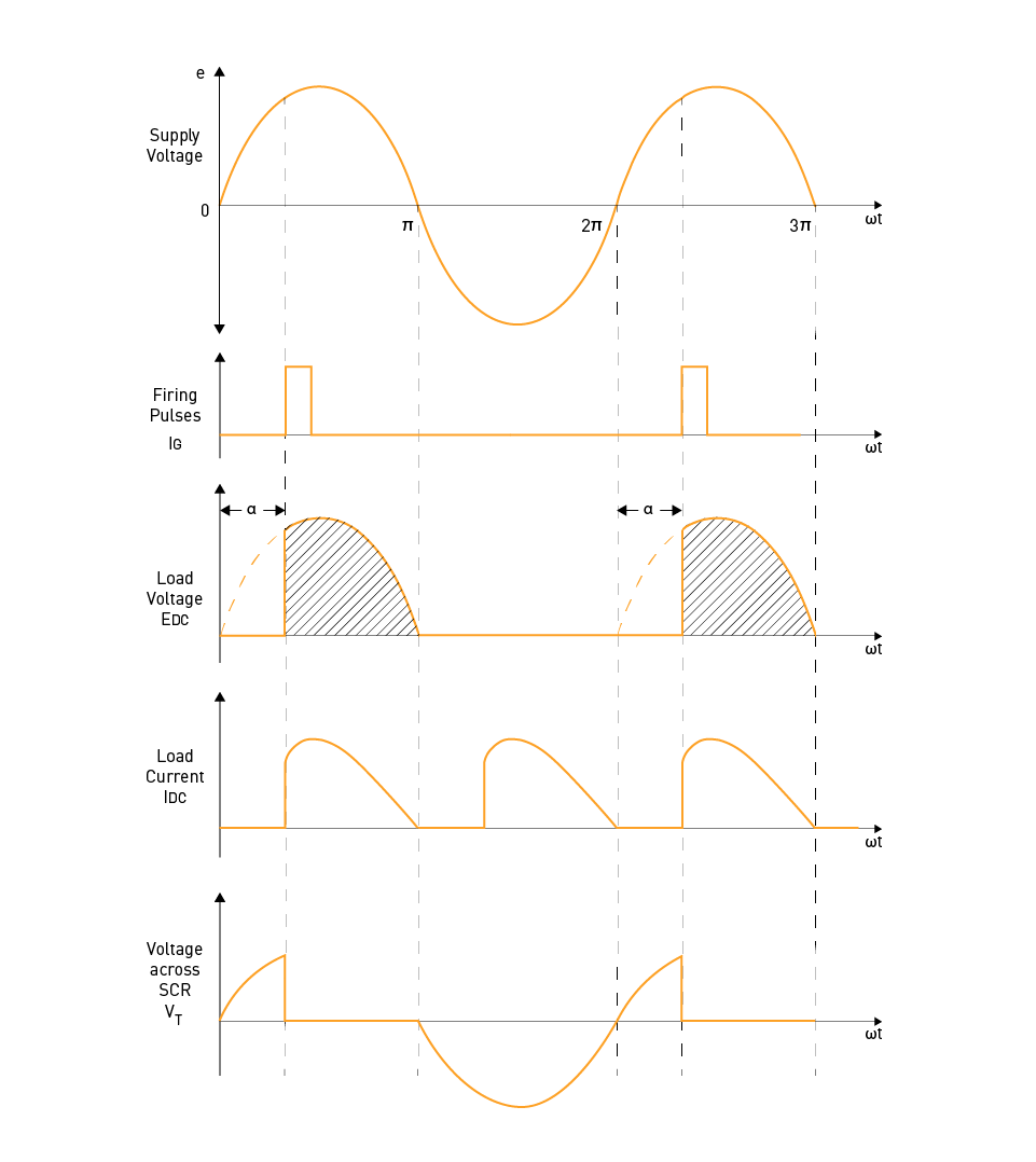
Figure 7: Single-phase half-wave controlled rectifier circuit (top) and waveforms (bottom)
Full-Wave Controlled Rectifiers
Full-wave controlled rectifiers employ two or more thyristors and are more efficient than their half-wave counterparts. These rectifiers utilize both the positive and negative half-cycles of the input AC supply. There are two main types of full-wave controlled rectifiers: the midpoint configuration and the bridge configuration.
Midpoint Configuration
The midpoint or center-tapped configuration is a setup that employs a center-tapped transformer and two thyristors. The secondary winding of the transformer is divided into two halves, with the midpoint connected to the load. The thyristors are linked between the ends of the secondary windings and the load. By sequentially triggering the thyristors, the rectifier conducts during both positive and negative half-cycles of the input AC supply, enabling control of the output voltage by adjusting the firing angle. However, a disadvantage of this configuration is that it necessitates a center-tapped transformer, which can be costly and cumbersome.
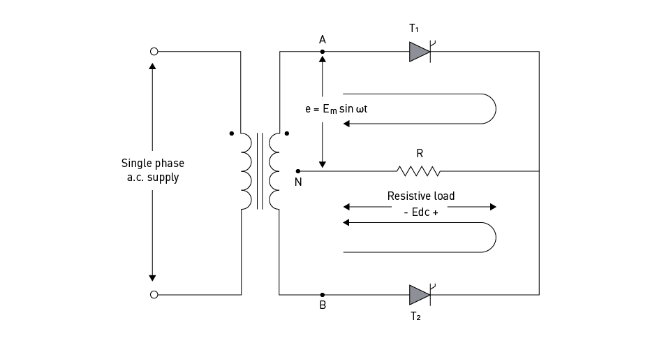
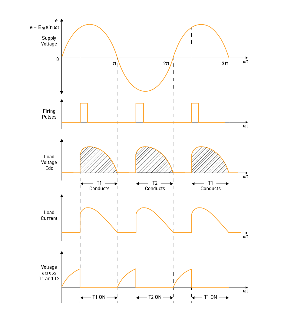
Figure 8: Single-phase full-wave controlled rectifier with midpoint configuration - circuit (top) and waveforms (bottom)
Bridge Configuration
The bridge configuration is a type of phase-controlled rectifier that uses four thyristors arranged in a bridge topology. This eliminates the need for a center-tapped transformer, making it a more compact and cost-effective design. In the bridge configuration, during the positive half-cycle, two diagonally opposite thyristors conduct, and during the negative half-cycle, the other two thyristors conduct. By adjusting the firing angles of the thyristors, the output voltage can be controlled. Compared to the midpoint configuration, bridge rectifiers have several advantages, including higher efficiency, better power factor, and lower harmonic distortion.
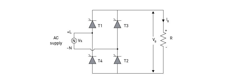
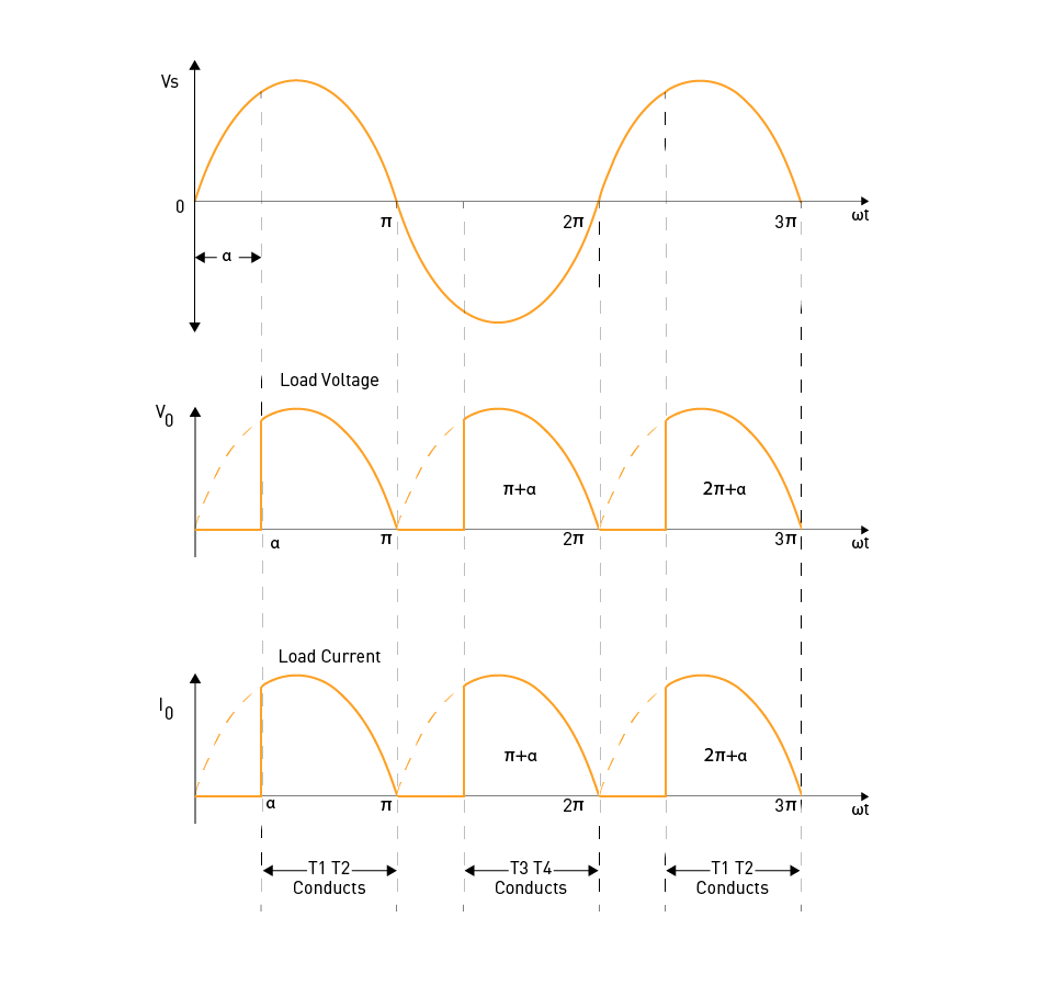
Figure 9: Single-phase full-wave controlled rectifier in the bridge configuration - circuit (top) and waveforms (bottom)
The performance of a single-phase controlled rectifier is assessed based on parameters such as the average output voltage, output current, ripple factor, power factor, and total harmonic distortion. Control techniques for adjusting the firing angle include constant firing angle control, integral cycle control, and pulse-width modulation.
Constant Firing Angle Control
Constant firing angle control is a technique in which the thyristors' firing angle is kept fixed during the rectification process. This approach offers a straightforward way to regulate the average output voltage. However, it can lead to issues with power factor and harmonic distortion, especially at lower output voltage levels.
Integral Cycle Control
Integral cycle control is a method of controlling the output voltage by switching the thyristors on and off for a fixed number of complete input voltage cycles. This method can help to improve the power factor and reduce harmonic distortion. However, it may also cause significant output voltage and current ripples, which can lead to additional noise and unwanted effects in some applications.
Pulse-Width Modulation
Pulse-width modulation (PWM) is an advanced control technique used to dynamically vary the firing angles of thyristors to achieve a desired output voltage waveform. By carefully selecting the firing angles, PWM can minimize harmonic distortion, improve power factor, and provide better output voltage regulation. However, PWM-controlled rectifiers require more complex control circuitry and may need advanced digital controllers or microprocessors.
Applications of Single-Phase Controlled Rectifiers
Single-phase controlled rectifiers find wide applications in a range of fields, including battery charging, variable-speed motor drives, power supplies for electronic devices, and electric vehicle charging stations, among others. With their ability to regulate the output voltage and handle high power levels, these rectifiers are suitable for diverse industrial, commercial, and residential applications.
In conclusion, It is important to note that single-phase controlled rectifiers are widely used in power electronics due to their ability to efficiently and precisely convert AC power to DC power. Engineers can use their knowledge of the operating principles, performance parameters, and control techniques to design and implement these devices in a range of applications. As technology and control strategies continue to advance, single-phase controlled rectifiers will remain a critical component in meeting the demands of modern electrical systems.
Semi/Dual/Full/ Series Converters
Based on the type of converters used to control the output voltage, Single-phase controlled rectifiers can be classified into several categories, these categories include semi-converters, dual, full, and series converters.
Single-Phase Dual-Converters
Dual converters belong to the category of single-phase controlled rectifiers and have the ability to deliver both positive and negative half-cycles of the input voltage to the load. This makes them more versatile than half-wave converters. Dual converters are made up of two converters, with one operating as a rectifier and the other as an inverter, enabling them to be used in applications that require bidirectional power flow. Furthermore, dual converters are specifically designed for four-quadrant operation, and they are commonly used in reversible and variable-speed DC drives.
The first quadrant is for forward motoring, where converter 1 is ON in rectifier mode, and the firing angle of the thyristors is lower than 90 degrees. The second quadrant is for regenerative braking, where converter 2 is ON in inverter mode, and the firing angle of the thyristors is greater than 90 degrees. The third quadrant is for reverse motoring, where converter 2 is ON in rectifier mode, and the firing angle of the thyristors is lower than 90 degrees. And the fourth quadrant is for regenerative braking, where converter 1 is ON in inverter mode, and the firing angle of the thyristors is greater than 90 degrees.
Although dual converters provide greater versatility and bidirectional power flow, their higher complexity and component requirements makes them costlier and more complexity as compared to semi-converters and single-phase full-wave controlled rectifiers. Additionally, dual converters may generate higher levels of harmonic distortion in the input current, leading to increased power losses in transmission and distribution systems, as well as electromagnetic interference issues. Thus, careful evaluation of the trade-offs between various rectifier types is critical for designing efficient and high-performing power electronics systems.
Single-Phase Semi-Converters
A single-phase semi-converter is composed of two thyristors or SCRs and two diodes. SCRs, which act as solid-state switches, enable current to flow in one direction when triggered. These devices are also known as thyristors. In a single-phase semi-converter, one diode and one SCR control the positive half-cycle of the AC input voltage, and the other diode and SCR control the negative half-cycle. The average DC voltage delivered to the load can be adjusted by controlling the timing of the trigger pulses to the SCRs. The conduction angle of the SCR is the period during which the thyristor is in a forward-biased state, conducting current. The timing of the thyristor trigger pulse with respect to the zero-crossing point of the AC waveform determines the conduction angle, which can be modified by adjusting the timing of the trigger pulse, allowing control of the average DC voltage delivered to the load.
Semi-converters provide a simple and effective way to control the DC voltage delivered to a load using two SCRs and two diodes. However, their output voltage is limited to 64% of the peak input voltage (will be explained in digression below), and the average DC voltage delivered to the load is lower than that of a full-wave rectifier. If the peak input voltage is designated as VP, and the firing angle of a SCR as α, the average value of the output voltage is equal to:
$$V_{DC} = \frac{V_P}{\pi} (1 + \cos\alpha)$$Thus, the maximum output voltage is:
$$V_{DC_{max}} = \frac{2 \cdot V_P}{\pi} \approx 0.64 \cdot V_P$$A single-phase semi-converter performs only one quadrant operation, which is forward motoring in the I quadrant. Careful consideration of the trade-offs between different types of rectifiers is essential when designing power electronics systems to ensure optimal performance and efficiency.
Single-Phase Full Converters
Single-Phase Full converters utilize four SCRs to deliver a constant DC output voltage. Like dual converters, full converters offer an uninterrupted output voltage and support bidirectional power flow. With the implementation of four SCRs, the full converter is capable of providing a continuous output voltage for both positive and negative half-cycles of the AC input voltage.
A full converter operates in two quadrants: forward motion in the I quadrant and reverse braking in the IV quadrant. During forward motion, the input voltage is applied to the load in the same polarity as the output voltage. During reverse braking, the input voltage is applied to the load in the opposite polarity as the output voltage, allowing the load to dissipate energy as heat or return energy to the power source. This makes full converters suitable for applications such as DC motor drives, where bidirectional power flow is required for motoring and braking operations.
A single-phase full converter can operate in two quadrants: the first quadrant (I) for forward motion and the fourth quadrant (IV) for reverse braking. During the first quadrant operation, the input voltage is supplied to the load in the same polarity as the output voltage, while during the fourth quadrant operation, the input voltage is applied to the load in the opposite polarity as the output voltage. This allows the load to either dissipate energy as heat or return energy to the power source, making full converters ideal for bidirectional power flow applications like DC motor drives, where both motoring and braking operations are needed.
Full converters offer bidirectional power flow and a continuous output voltage, requiring four SCRs and additional control circuits. Full converters can generate higher levels of harmonic distortion in the input current, which may lead to issues such as increased power losses and electromagnetic interference. Therefore, it is crucial to carefully evaluate the trade-offs among different types of rectifiers when designing power electronics systems to achieve optimal efficiency and performance.
Single-Phase Series Converters
Series converters use a combination of semi-converters and dual converters to provide both positive and negative output voltages. They consist of two semi-converters and a dual converter connected in series. Series converters are commonly used in applications that require high power and precise control of the output voltage.
Three-Phase Controlled Rectifiers
Three-phase controlled rectifiers are a widely used component in power electronics that are utilized to convert three-phase AC power to DC power. These rectifiers find applications in various fields such as power supplies, variable-speed drives, and motor controllers. The fundamental configuration of a three-phase controlled rectifier comprises six diodes arranged in a bridge topology, along with thyristors or other semiconductor switches connected in parallel with the diodes to regulate the output voltage of the rectifier. There are two main types of three-phase controlled rectifiers: six-pulse and twelve-pulse rectifiers. Six-pulse rectifiers are the simplest and most commonly used. They have three thyristors connected in series in each phase of the rectifier circuit, which are fired in sequence to produce a pulsed output voltage. The output voltage is then smoothed using a filter capacitor to produce a DC voltage.
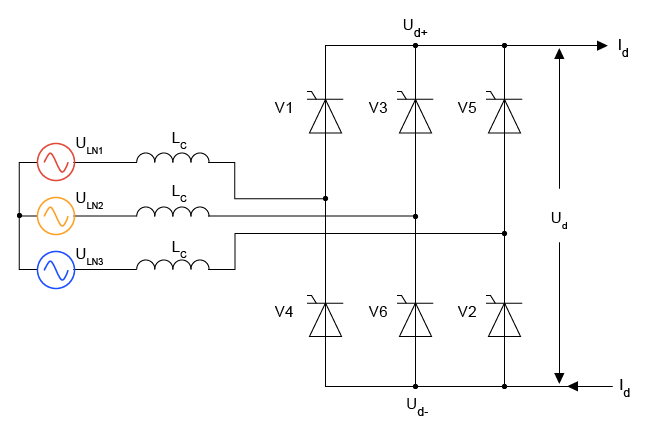
Figure 10: Three-Phase 6-Pulse Full-Wave Controlled Rectifier
On the other hand, twelve-pulse rectifiers have two six-pulse rectifiers connected in parallel to produce a smoother DC output voltage. They require a more complex control system to synchronize the two rectifiers.
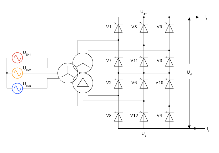
Figure 11: Three-Phase 12-Pulse Full-Wave Controlled Rectifier
Three-phase controlled rectifiers offer several advantages over single-phase controlled rectifiers, including higher power output, lower harmonic distortion, and better efficiency. However, they are more complex and require a more sophisticated control system. Additionally, they require a larger number of semiconductor switches, which can increase the cost of the rectifier circuit.
Input Current Harmonic Distortion
Industrial applications widely utilize three-phase controlled rectifiers because of their ability to provide adjustable DC voltage with modifiable power. However, these rectifiers have a significant disadvantage in the form of input current harmonic distortion. The rectifier circuit's non-linear nature results in the input current containing harmonics that can cause disturbances in the power system, adversely affecting other connected equipment's performance. The total harmonic distortion (THD) factor can be used to measure the input current harmonic distortion. The THD factor represents the ratio of the root-mean-square (RMS) value of the harmonic content of the input current to the RMS value of the fundamental frequency component. A high THD factor can cause voltage distortion, reduce power quality, and increase power losses.
It is therefore essential to minimize the THD factor to improve the performance and reliability of the power system. Different control strategies can be used to reduce the input current harmonic distortion in three-phase controlled rectifiers, such as harmonic injection, pulse skipping, and space vector modulation.
Output Ripple Voltage
The output ripple voltage in three-phase controlled rectifiers refers to the DC output voltage's fluctuation from its intended constant value. This ripple voltage is a result of the rectified output waveform's pulsating nature, caused by the thyristors' switching action.
The amplitude of the output ripple voltage in three-phase controlled rectifiers is directly proportional to both the load current and the frequency of the AC input voltage. Therefore, if the load current increases or the input voltage frequency decreases, the amplitude of the output ripple voltage will increase as well. This increase in ripple voltage reduces the overall quality of the DC output voltage.
To reduce the output ripple voltage in three-phase controlled rectifiers, various techniques are utilized, such as capacitive, inductive, and LC filtering. These filtering techniques utilize passive components, including capacitors and inductors, to smooth out the pulsating DC output waveform and decrease the amplitude of the output ripple voltage.
The choice of filtering technique depends on the specific application and the level of ripple reduction required. Capacitive filtering is a simple and cost-effective method, but it is less effective in reducing higher-order harmonics. Inductive filtering is more effective in reducing higher-order harmonics, but it is more complex and expensive. LC filtering provides the highest level of ripple reduction but is also the most complex and expensive filtering technique.
Reducing the output ripple voltage is crucial for maintaining a stable and consistent DC output voltage in three-phase controlled rectifiers. The implementation of filtering techniques can effectively decrease the amplitude of the output ripple voltage and enhance the overall quality of the DC output voltage.
Efficiency
Efficiency is a crucial factor in the design and operation of three-phase controlled rectifiers. The rectifier efficiency is defined as the ratio of the DC output power to the total input power. In three-phase controlled rectifiers, several factors can impact the efficiency, such as the control strategy employed, load characteristics, and switching frequency.
The highest rectifier efficiency is usually achieved when the output voltage and current are constant, and the losses are minimized. However, in practical applications, the output voltage and current may not be constant, and the rectifier may encounter losses due to switching, conduction, and other factors. To improve efficiency, it is necessary to reduce the losses in the rectifier circuit.
The utilization of a high-frequency switching scheme, such as pulse-width modulation (PWM) control, can decrease switching losses and enhance the rectifier's efficiency, thereby reducing losses. Additionally, implementing soft-switching techniques, such as resonant switching, can lower the voltage and current stresses on the switching devices and improve the overall efficiency of the rectifier.
It's important to keep in mind that the efficiency of a three-phase controlled rectifier may fluctuate based on the load conditions. For instance, idle losses in the circuit may significantly reduce the efficiency at low load conditions. Therefore, it is essential to consider load conditions while designing and operating three-phase controlled rectifiers to optimize their efficiency.
Semi / Dual / Full / Series Converters
Three-Phase Semi-Converters
Three-phase semi-converters, which are also known as half-controlled converters, utilize both diodes and thyristors to rectify three-phase AC voltage. These converters include a bridge configuration consisting of three diodes and three thyristors. By firing the thyristors at a specific angle, α, the current flowing through the load can be controlled. Semi-converters are commonly used in applications that require unidirectional power flow and have an inductive load, such as battery chargers and DC motor drives.
Advantages of three-phase semi-converters include:
- Simpler circuitry compared to full-converters, reducing the overall cost.
- Smoother output voltage waveform and reduced harmonics compared to single-phase converters.
However, three-phase semi-converters exhibit a discontinuous output current, which may require additional filtering.
Three-Phase Full Converters
Three-phase full-converters, unlike semi-converters, utilize six thyristors in a bridge configuration to provide full control over the rectification process. By adjusting the firing angle of the thyristors, the output voltage can be precisely controlled. These converters are ideal for applications that require bidirectional power flow and accurate voltage control, such as regenerative braking systems, variable-frequency drives, and high-power battery chargers.
Advantages of three-phase full-converters include:
- Continuous and controllable output current.
- Greater control over output voltage and power factor.
- Improved efficiency due to bidirectional power flow.
However, full-converters have a higher harmonic content compared to semi-converters and require more complex control circuitry.
Three-Phase Dual-Converters
Three-phase dual-converters consist of two three-phase full-converters, which can be connected in parallel or series to enable four-quadrant operation. With this configuration, the converter can control not only the output voltage magnitude but also the polarity, which makes it ideal for applications requiring rapid direction reversal or dynamic torque control, such as large cranes, elevators, or electric vehicles.
Advantages of three-phase dual-converters include:
- Four-quadrant operation, providing greater control over motor torque and speed.
- Bidirectional power flow, allowing for energy recovery in regenerative braking systems.
- Enhanced dynamic response due to independent control of voltage and polarity.
However, three-phase dual-converters are more complex and expensive compared to other types of controlled rectifiers, making them suitable for high-performance applications where precise control and rapid response are essential.
Advanced Control for Harmonic Reduction and Power Factor Improvement
Extinction Angle Control
Extinction angle control is a power electronics technique used to enhance power factor and decrease harmonic distortion in AC power systems. It is typically used in AC voltage regulators and AC motor speed controllers. This method involves delaying the turn-on time of a thyristor in a controlled rectifier circuit in each half-cycle of the AC waveform. The delay is called the extinction angle, and by adjusting it, the power delivered to the load can be regulated, leading to an improvement in the power factor and a reduction in harmonic distortion.
Extinction angle control is a useful method for regulating the output voltage of AC voltage regulators, particularly in high-power applications. It enables the regulator to maintain a steady output voltage despite changes in the load while keeping power factor and harmonic distortion at acceptable levels. This technique is a valuable tool for power electronics engineers as it enhances efficiency, improves power quality, and minimizes electromagnetic interference, all of which are crucial for modern power systems.
Symmetrical Angle Control
The use of symmetrical angle control in power systems can enhance power factors and diminish harmonics. Essentially, this method involves managing the timing of the switching devices within the power converter (such as thyristors or IGBTs) to guarantee that the input current waveform mimics the input voltage waveform. This process results in an improved power factor and lessened harmonics within the system.
The adjustment of the on-time and off-time of the switching devices is essential in symmetrical angle control to attain the intended input current waveform. This adjustment is commonly executed by modifying the phase angle or delay between the voltage and current waveforms, which are also referred to as the firing or conduction angles. Precise control of the firing angle permits the shaping of the input current waveform to achieve a more sinusoidal shape, thus reducing harmonic distortion.
Symmetrical angle control is a frequently employed technique in high-power applications such as motor drives, mainly to enhance system efficiency and minimize electromagnetic interference. It is an intricate control method that necessitates sophisticated control algorithms and precise timing control of the switching devices. Nevertheless, when applied appropriately, symmetrical angle control can notably advance power factor and curtail harmonic distortion.
Constant Voltage Control
Constant voltage control is a technique employed to regulate the output DC voltage of the rectifier to a fixed value, irrespective of changes in input AC voltage or load conditions. This is accomplished using a feedback loop that constantly supervises the output DC voltage and adapts it to maintain the desired value. Typically, a voltage regulator is utilized to implement constant voltage control, which receives the rectifier's output DC voltage as input and compares it to a reference voltage that represents the intended output voltage. If there is any deviation between the output DC voltage and the reference voltage, the voltage regulator adjusts its output to rectify the deviation and return the output DC voltage to the desired value.
Two primary types of voltage regulators exist: linear and switching regulators. Linear regulators utilize a transistor to control the output voltage, while switching regulators adjust the output voltage by utilizing pulse width modulation (PWM) techniques. Each type of voltage regulator has its advantages and disadvantages, and the selection depends on specific application requirements. In the linear regulator, a constant voltage at the base of the transistor is provided by the zener diode, requiring a continuous flow of current. The collector's current is the sum of the load current and the zener diode current, resulting in the generation of unnecessary power losses through a series limiting resistor.
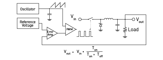
Figure 12: PWM voltage regulator circuit (block diagram)
A pulse-width-modulated circuit is needed to eliminate inherent inefficiencies in a linear regulator.
The triangle/trapezoid wave, with reference frequency, is generated by the oscillator. The reference voltage is compared with the output voltage. Both signals are going to an error amplifier that amplifies the difference between these values. The resulting signal (signal which goes from the error amplifier) is sent to Pulse Width Modulator. The PMW compares the resulting signal amplitude with the trapezoid signal generated by the oscillator to determine how long the pulses will come out of the circuitry.
The output voltage is calculated using the following equation:
$$V_{out} = \frac{V_{in} \cdot T_{on}}{T_{on} + T_{off}}$$Where:
Vin – input voltage
Ton – time interval (in one cycle) for which the signal which goes from the error amplifier is lower than the signal generated by the oscillator
Toff - time interval (in one cycle) for which the signal which goes from the error amplifier is greater than the signal generated by the oscillator
During the time interval Ton, the switch is closed. The inductor begins to charge and creates a magnetic field. Also, the capacitor begins to charge and creates its electric field. Now, when the switch is turned off (during the time interval Toff), the inductor’s magnetic field will collapse, and it will cause current to flow through the zener diode into the ground. So, the energy stored in the inductor will supply the load in the direction from ground to Vout potential. The capacitor’s electric energy will discharge, and its current will flow through the load in the same direction. With a given load current, the output voltage will stay stable. So, the entire pulse was sufficient to provide desired output voltage value.
When the load goes up, the output voltage value will drop when there is a greater current demand. The difference between the reference voltage and the output voltage will be greater than the error, and the error voltage will be created at the output of the error amplifier. Compared with the trapezoid signal in the PWM, the sum voltage value will be reduced. Because of that, the time interval Toff will also be decreased, and the time interval Ton will increase. This means that the inductor’s magnetic and capacitor’s electric field will be large enough to meet the load demand during the new Toff period. This way, the output voltage will stay stable when the load increases. The same approach also applies when the input voltage changes.
Constant voltage control is a fundamental aspect of regulating the output DC voltage of a rectifier, ensuring stability and reliability even in the face of input AC voltage fluctuations or load changes. This feature is especially critical in applications that require precise and consistent DC voltage supplies. Constant voltage control can improve energy efficiency and reduce operational costs in the long run by lowering power losses and enhancing the power factor.
In Conclusion, understanding the principles and implementation of continuous voltage control is crucial in designing and maintaining efficient and high-quality power electronics systems. The selection of the voltage regulator is crucial in achieving the desired level of constant voltage control. Proper design and control of the rectifier circuit are essential to ensure dependable operation in a variety of applications.
Constant Current Control
Another widely used control technique for three-phase diode rectifiers is constant current control, which aims to maintain a fixed output DC regardless of variations in the input AC voltage or load conditions.
One way to achieve constant current control is through a feedback loop that monitors the direct current output and makes adjustments to maintain the desired value. This feedback loop can be implemented with a current regulator, which compares the output direct current to a reference current representing the desired output. If the output DC differs from the reference current, the regulator adjusts its output to correct the difference and bring the output DC back to the desired value.
Various methods exist for implementing constant current control, depending on the application's particular needs. A widely used technique is utilizing a shunt regulator, which is a linear regulator that manages the output current by modifying the shunt resistor's resistance. Another approach is to use a switching regulator, such as a buck converter or boost converter, which adjusts the duty cycle of a switching transistor to regulate the output current more efficiently.
Constant current control is a favorable control strategy in comparison to other control methods, mainly in applications where precise current regulation is necessary or where highly variable loads are involved. By regulating the rectifier's output current, constant current control can enhance system stability and reliability, reduce the risk of overloading or overheating, and offer better protection against faults like short circuits. Furthermore, constant current control can improve the power factor of the system, which reduces overall power losses and enhances energy efficiency.
To summarize, constant current control is a crucial control strategy for three-phase diode rectifiers, especially in applications that require precise current regulation or highly variable loads. Familiarity with the principles and implementation of constant current control is necessary to design and sustain efficient and high-quality power electronics systems.
Voltage-Fed PWM Control
Voltage-fed pulse width modulation (PWM) control is a prevalent method for regulating three-phase diode rectifiers, and its working principle is simple. The control system employs a high-frequency pulse generator to create a PWM signal that operates the rectifier's switching devices. The pulse generator produces a signal with a constant frequency and a varying duty cycle that determines the on and off times of the switching devices. As the duty cycle of the PWM signal rises, the voltage supplied to the load also increases.
Implementing voltage-fed PWM control comprises two primary stages: the pulse generator and the switching devices. The pulse generator can be realized through an analog or digital circuit utilizing a microcontroller. The analog circuit produces a sawtooth waveform that it compares with a reference voltage to create the PWM signal. Conversely, the digital circuit leverages a microcontroller and a set of predetermined algorithms to generate the PWM signal.
Voltage-fed pulse width modulation (PWM) control is widely used for power electronic applications. The switching devices used in PWM control are crucial components in this system, as they regulate the voltage output. There are various technologies available for implementing these switching devices, including bipolar junction transistors (BJTs), metal oxide semiconductor field-effect transistors (MOSFETs), and insulated-gate bipolar transistors (IGBTs).
MOSFETs and IGBTs are the most frequently used switching devices in voltage-fed PWM control among the available technologies. Their high efficiency is one reason for this, making them a desirable option for low power loss applications. MOSFETs and IGBTs also possess fast switching speeds, enabling them to operate at high frequencies.
Another factor that contributes to the widespread use of these devices in voltage-fed PWM control is their ease of implementation. MOSFETs and IGBTs come in various sizes and voltage ratings, making them versatile and adaptable to different applications.
Voltage-fed PWM control provides numerous benefits in regulating three-phase diode rectifiers. The high-frequency PWM signal minimizes harmonic distortion in the output voltage waveform, resulting in improved efficiency and less noise. The PWM signal's variable duty cycle regulates the output voltage, enabling the control system to sustain a constant output voltage under varying input voltage and load conditions.
Voltage-fed PWM control is exceptionally effective in regulating three-phase diode rectifiers, and its advantages, including enhanced efficiency, reduced harmonic distortion, and precise output voltage regulation, make it a popular option for various power electronics applications. Understanding the principles and implementation of voltage-fed PWM control is essential for developing and maintaining high-quality, efficient power electronics systems.
Current-Fed PWM Control
Current-Fed Pulse Width Modulation (PWM) Control is a widely used control strategy in three-phase diode rectifiers that provides precise control of the output current. It controls the output current through a feedback loop that adjusts the input voltage to the rectifier circuit.
In Current-Fed PWM Control, the input voltage to the rectifier circuit is controlled using a series resonant circuit. This resonant circuit is inserted between the source and the rectifier and acts as a buffer. It is tuned to the frequency of the input voltage, and the voltage across the resonant circuit is used to control the switching of the rectifier. This control scheme allows for better management of the input current and voltage, resulting in improved efficiency and reduced electromagnetic interference. Furthermore, it is possible to design the resonant circuit in a way that enables soft switching, reducing the strain on the switching devices and prolonging their lifespan. Current-Fed PWM Control is typically utilized in high-power applications such as motor drives and power supplies. To ensure a constant output current, the PWM signal regulates the switching of the rectifier by modifying the duty cycle of the switching signal.
The generation of the PWM signal in Current-Fed PWM Control involves continuously monitoring the output current and adjusting the duty cycle of the switching signal in response to a reference current. This feedback loop allows for the maintenance of a constant output current, even when there are changes in the input voltage or load.
Compared to other methods for controlling three-phase diode rectifiers, Current-Fed PWM Control offers high efficiency, low harmonic distortion, and accurate control of the output current, which helps reduce the rectifier circuit's impact on the power system. However, this method has some limitations. It requires the use of a resonant circuit, which acts as a buffer and is tuned to the input voltage's frequency to control the switching of the rectifier. Implementing the resonant circuit can be challenging and costly. Furthermore, the system's stability of the output current can be affected by variations in the load, which may limit its reliability in some applications.
In conclusion, current-Fed PWM Control is an effective control method for three-phase diode rectifiers that offers accurate output current control and high efficiency. However, its application can be complicated and susceptible to changes in the load. Therefore, it is crucial to comprehend the principles and implementation of Current-Fed PWM Control to design and maintain efficient power electronics systems.
SPWM Control
Sinusoidal Pulse Width Modulation (SPWM) is a popular technique for improving power factors and reducing harmonic distortion in power electronics. In SPWM, the reference waveform is compared to a high-frequency triangular waveform, and the difference between the two is used to generate a series of pulses with varying widths. These pulses are then applied to the switching devices, such as MOSFETs or IGBTs, to control the output voltage or current waveform. By adjusting the amplitude and frequency of the reference and carrier waveforms, SPWM can generate high-quality sinusoidal waveforms with minimal harmonic distortion and high power factor. SPWM is particularly useful in applications like motor drives and renewable energy systems, as it can greatly enhance the efficiency and dependability of power electronics systems.



直接登录
创建新帐号