Introduction to Three-Phase AC/AC Converters
Three-phase AC/AC converters convert and regulate the RMS voltage and frequency of three-phase alternating current (AC) electrical systems. They are frequently used in a variety of industrial applications because they can withstand larger power levels, have more dependability, and perform better than single-phase AC/AC converters. Three-phase AC/AC converters are appropriate for heavy-load applications such as motor drives, uninterruptible power supply (UPS), and large-scale power systems.
The fundamental goal of three-phase AC/AC converters is to maintain the input frequency while regulating the output voltage's RMS magnitude and/or phase angle. They are divided into two types: three-phase AC voltage controllers and three-phase AC choppers. To control the output voltage waveform, both types of converters use power electronic switches such as Insulated Gate Bipolar Transistors (IGBTs), Metal-Oxide Semiconductor Field-Effect Transistors (MOSFETs), or Thyristors.
The principles of operation, types of loads, control methods, voltage control techniques, and applications of three-phase AC voltage controllers and three-phase AC choppers will be covered in this section. Understanding the essential ideas and characteristics of three-phase AC/AC converters can assist students and engineers in designing and implementing efficient and dependable power electronic systems for a variety of applications.
Three-Phase AC Voltage Controllers
Principle Of Operation
Multiple topologies of three-phase AC voltage controllers can be utilized to provide three-phase loads with variable RMS AC voltage. The operation of the arrangement indicated in Figure 3 (left) will be discussed below. This arrangement is distinguished by the inability of individual phase regulator currents to be individually changed. To establish the load current, at least two thyristors must be turned on at the same time.
The regulator operates symmetrically if the firing pulses of the thyristors in each phase have the same sequence relative to the voltages of the three-phase system generator (input voltage). Thus, the firing pulses of thyristors T3 and T6 must lag the firing pulses of thyristors T1 and T4 by an angle of 2π/3, respectively, and the firing pulses of thyristors T5 and T2 must lag the firing pulses of thyristors T1 and T4 by an angle of 4π/3. In addition, the firing pulses of thyristors in the same phase must be shifted by an angle of π, so the thyristors must be turned on in the sequence T1, T2, T3, T4, T5, T6, T1, T2, ... with a spacing of π/3. Given the requirement of conducting at least two thyristors, each thyristor must have a confirmation pulse that is delayed by π/3 in addition to the firing pulse. Once the firing pulse sequence is known, the reference instant relative to which the firing angle is measured must be determined. The highest load current is sought for a firing angle of α = 0 degrees because the thyristors conduct as quickly as feasible. If the load is directly linked to the input voltage, the maximum load current is attained, and given the resistive load, the current of independent loads have the same waveform as the phase voltages of the three-phase system. As a result, when α = 0 degrees, the moment of crossing the phase voltage through zero is measured. The operation of this regulator will be examined for the characteristic firing angle of 30 degrees. Figure 3 (right) depicts the waveforms of the voltage on the load, i.e., load current.
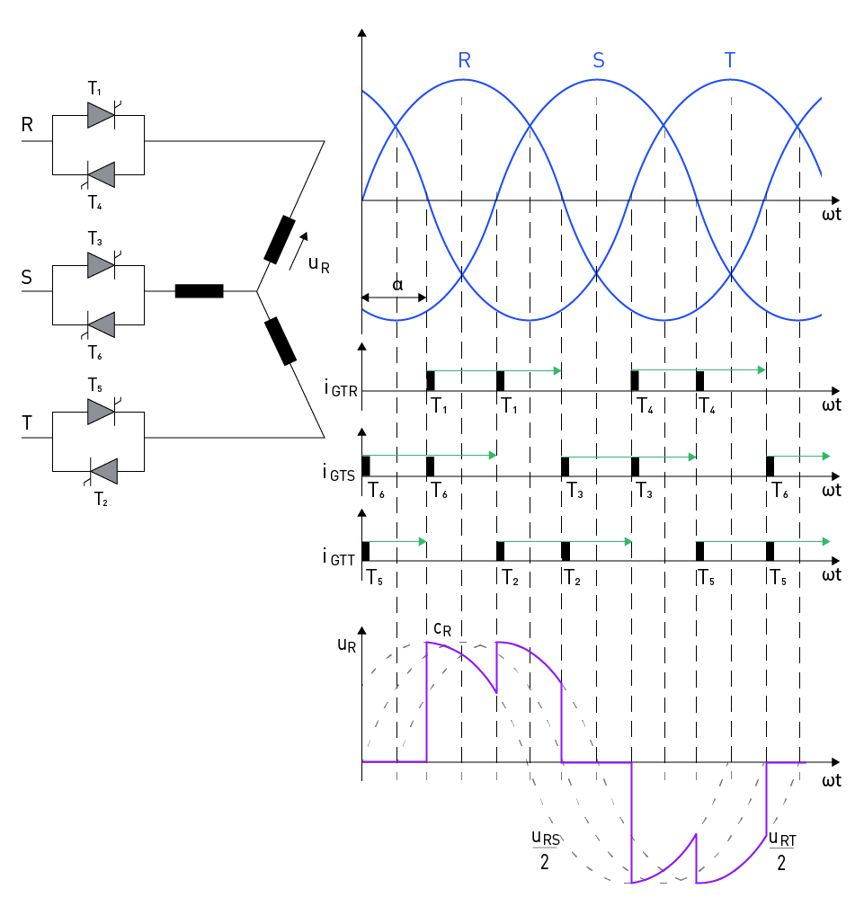
Figure 3: Three-phase AC voltage controller
For a firing angle of α = 60 degrees, at time ωt = α, thyristor T1 gets a firing impulse while thyristor T6 receives a confirmation impulse, causing both thyristors to conduct and the load voltage to become half of the line voltage uRS. Thyristor T2 gets a firing impulse at time ωt = α + π/3, causing all three phases (T1, T2, and T6) to conduct and the load voltage to become the phase voltage eR.
At the same time, the phase voltage eS drops to zero and begins to reverse direction, forcing T6 to cease conducting and only T1 and T2 to continue conducting, leading the load voltage to drop to half of the line voltage uRT. Thyristor T3 is activated at time ωt = α + 2π/3, causing the voltage eR to equal zero and reverse direction, forcing T1 to quit conducting. This operating mode is suitable for firing angles ranging from 60 degrees to 90 degrees.
Three-phase AC voltage controllers are power electronic converters that alter the firing angle of the power semiconductor switches to regulate the RMS and phase angle of the output voltage. The primary switching devices in these controllers are thyristors or triacs, which are coupled in various topologies such as antiparallel or series. The functioning of a three-phase AC voltage controller is based on the phase control concept, in which the firing angle of each thyristor is modified to regulate the conduction period and, as a result, the output voltage waveform.
Types Of Loads And Their Effects
Three-phase alternating current voltage controllers are used with a variety of loads, including inductive, resistive, and capacitive loads. The load type has a considerable influence on the voltage controller's performance and characteristics.
Resistive Loads: In completely resistive loads, the current waveform follows the voltage waveform with no phase shift. The controller's function stays straightforward, and harmonic distortion is kept to a minimum.
Inductive Loads: Motors and transformers, for example, introduce a phase shift between the voltage and current waveforms, influencing the firing angle and conduction time. This can lead to greater harmonic distortion and a drop in power factor, requiring extra control and filtering measures.
Capacitive Loads: Capacitive loads can cause voltage and current waveforms to be out of phase, complicating control strategy and potentially leading to voltage controller instability.
Control Strategies
In three-phase AC voltage controllers, several control algorithms may be used to optimize performance, minimize harmonic distortion, and enhance power factor. Control methods that are regularly employed include:
Phase Angle Control: To manage the output voltage, this approach includes altering the firing angle of each thyristor. Delaying the firing angle reduces the effective output voltage, allowing for continuous adjustment of the output voltage.
Integral Cycle Control: This approach includes turning on and off the thyristors for a predetermined number of cycles, resulting in discrete control of the output voltage. When compared to phase angle control, this method is best suited for low-frequency applications since it lowers harmonic distortion.
Hysteresis Control: This approach works by altering the firing angle of the thyristors to keep the RMS output voltage within a preset hysteresis band. This strategy improves dynamic responsiveness but may increase harmonic distortion.
The proper control technique is determined by the unique application requirements, such as load type, desired output voltage range, and system stability.
Three-Phase AC Choppers
Principle Of Operation
Three-phase AC choppers are power electronic devices that employ chopping the input voltage waveform to regulate the output voltage of a three-phase AC system. High-speed semiconductor switches, such as IGBTs or MOSFETs, are used in these converters to interrupt the input voltage for a set period during each half-cycle, thus controlling the output voltage. A three-phase AC chopper operates on the pulse-width modulation (PWM) principle, in which the duty cycle of the switches is modified to regulate the output voltage.
Voltage Control Techniques
In three-phase AC choppers, various voltage control approaches may be used to optimize performance, reduce harmonic distortion, and enhance power factor. Among the most prevalent voltage control strategies are:
Sinusoidal PWM: This approach generates PWM pulses by comparing a sinusoidal reference signal to a triangular carrier signal. The RMS output voltage and frequency are determined by the amplitude and frequency of the reference signal, respectively.
Space Vector Modulation (SVM): SVM is a sophisticated voltage control approach that represents three-phase voltages as a vector on a two-dimensional plane. The output voltage may be successfully controlled by adjusting the vector's location and magnitude.
Hysteresis Control: This approach works by altering the duty cycle of the switches to keep the output voltage within a preset hysteresis range. This strategy improves dynamic responsiveness but may increase harmonic distortion.
Applications
Because of its capacity to regulate the output voltage with great efficiency and quick dynamic response, three-phase AC choppers are employed in a broad range of applications. Among the most important uses are:
Motor Drives: Variable-speed motor drives, such as induction motor drives and synchronous motor drives, use three-phase AC choppers to change the motor's speed and torque by altering the RMS output voltage and frequency.
Power Factor Correction: Three-phase AC choppers can be used for power factor correction in industrial and commercial installations by adjusting the output voltage in accordance to the input current.
Renewable Energy Systems: Three-phase AC choppers can be used in wind energy and solar energy systems to manage output voltage and maintain acceptable power quality, especially when linked to the grid.
Uninterruptible Power Supply (UPS): Three-phase alternating current (AC) choppers can be used in UPS systems to adjust output voltage and protect sensitive loads from voltage variations and utility grid interruptions.
直接登录
创建新帐号