Introduction to Single-Phase AC/AC Converters
Power electronic devices such as single-phase AC/AC converters are used to regulate the RMS and/or phase of the voltage or current in single-phase alternating current (AC) systems. These converters may alter the AC waveform's RMS voltage, frequency, or phase angle, offering accurate control and better performance in a variety of applications. They are frequently employed in single-phase AC power systems, which are the most common type of electrical supply in residential, commercial, and light industrial settings.
The classification of single-phase AC/AC converters is done in two categories based on their operating principles:
- Phase-controlled AC voltage controllers
- Single-phase AC choppers
Each category has its unique characteristics, control strategies, and applications, as discussed in the following sections.
The fundamental ideas, guiding principles, and control strategies pertaining to single-phase AC/AC converters will all be covered in this chapter. It will also discuss how different loads affect these converters' performance and give an overview of how they are used in various power electronics systems. Engineers and students may efficiently build and optimize power electronics systems for a variety of applications, from motor speed control to lighting systems and beyond, by knowing the basic principles and methods of single-phase AC/AC converters.
Phase-Controlled AC Voltage Controllers
Principle Of Operation
A class of single-phase AC/AC converters known as phase-controlled AC voltage controllers, also referred to as phase-controlled regulators or thyristor-based AC controllers, use power electronic switches like thyristors, triacs, or silicon-controlled rectifiers (SCRs) to regulate the conduction angle or firing angle of these switches in order to control the RMS output voltage. The time when the thyristor is turned on and current can flow through the load is known as the conduction angle, indicated by γ. By changing the firing angle, the output voltage may be precisely controlled to the required level, giving the AC waveform control.
In a conventional phase-controlled AC voltage controller, the thyristors are coupled in an antiparallel fashion. By doing so, the controller is able to manage bidirectional current flow and regulate both the positive and negative half-cycles of the input AC waveform. The gating signals necessary to switch on the thyristors at the proper firing angle are produced by a control circuit, which frequently uses a microcontroller or a digital signal processor (DSP).
Types Of Loads And Their Effects
The type of load connected to the converter can have an effect on the performance of phase-controlled AC voltage controllers. Resistive, inductive, and capacitive loads are examples of common load types.
Resistive loads: The current waveform follows the voltage waveform with completely resistive loads, and the phase angle between voltage and current is zero. In this scenario, a phase-controlled AC voltage controller can offer smooth and continuous output voltage control with little distortion.
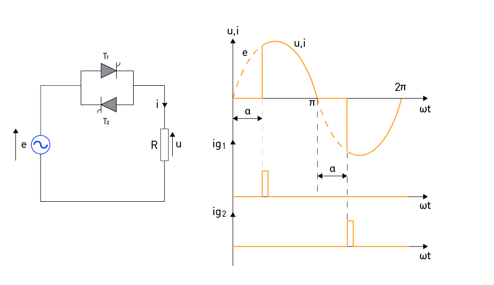
In Figure 1 (left), a single-phase AC voltage controller, with thyristors is connected in an antiparallel configuration. This configuration is commonly used because it involves a lesser number of switching elements, thus, resulting in the minimum losses. Due to the various potentials of the thyristor cathodes in this configuration, galvanic isolation of the control circuit is required. The idea behind controlling the output RMS voltage is based on the fact that the load is only intermittently linked to the input voltage throughout a half-cycle. When the thyristor is turned on (by applying a firing pulse), that moment determines how long this portion of the half-cycle lasts. The firing angle α, which denotes the amount of time between when the thyristor starts to become forward-biased and when it receives a firing pulse, defines this moment.
In Figure 1 (right), the waveforms for the input voltage, firing pulse, and output voltage (or current) are displayed. Thyristor T1 is forward-biased during the positive half-cycle of the input voltage.
As the load current falls to zero and the input voltage shifts directions, thyristor T1 becomes reverse-biased. This thyristor is activated by the ig1 pulse at time ωt = α and conducts until the conclusion of the half-cycle. Thyristor T1 will be in reverse bias for the duration of the following half-cycle, which is a lot longer than the time needed for it to turn off. The voltage across the load is equal to the input voltage while thyristor T1 is conducting. Similar events take place at the input voltage's negative half-cycle, with the exception that thyristor T2 conducts because it is then forward-biased.

Figure 1: Single-phase AC voltage controller with resistive (R) load
The firing angle of the thyristor can be altered from α = π to α = 0, which allows the output (load) voltage's RMS value to be adjusted from zero to the input voltage's RMS value. The output voltage's RMS value for the firing angle "α" is:
$$U=\sqrt{\frac{1}{\pi}\int_{\alpha}^{\pi}{\left(\sqrt2E\ sin\ \left(\omega t\right)\ \right)^2d\left(\omega t\right)}}$$By changing ωt = x:
$$U=E \cdot \sqrt{\frac{2}{\pi}\int_{\alpha}^{\pi}{\frac{1-cos\ 2x\ }{2}dx}}$$ $$\Leftrightarrow U=E\cdot\sqrt{\frac{2}{\pi}\cdot\left(\frac{\pi-\alpha}{2}-\frac{1}{4}\cdot\left(sin\ 2\pi\ -sin\ 2\alpha\ \right)\right)}$$ $$\Leftrightarrow U=E\cdot\sqrt{1-\frac{\alpha}{\pi}+\frac{sin\ 2\alpha\ }{2\pi}}$$where E is the RMS value of the input voltage and U is the RMS value of the output voltage.
Inductive loads: When an inductive load, such as a transformer or an induction motor, is connected to the converter, the current lags behind the voltage and causes a phase shift. This results in higher harmonic distortion and lower power factor. To diminish these effects, some additional measures, such as inductor current control, may be required.
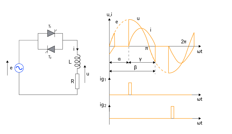
A single-phase AC voltage controller with a load represented by an inductor of inductance L coupled in series with a resistor of resistance R is depicted in Figure 2 (left). The waveforms of the input voltage, the output voltage and current, as well as the trigger pulses used to turn on the thyristor at the firing angle α are displayed in Figure 2 (right).

Figure 2: Single-phase AC voltage controller with LR load
Upon applying the trigger pulse to thyristor T1 at ωt = α, T1 conducts and the load voltage becomes equal to the input voltage. As thyristor T1 experiences voltage drop while conducting, thyristor T2 becomes reverse-biased. It is when thyristor T1 stops conducting at the moment ωt = β, thyristor T2 becomes forward-biased by the input voltage, which at that moment has a value of:
$$\sqrt{2}E\cdot\sin\beta$$This sudden rise in the voltage of forward-biasing of the thyristor leads to unintended turn-on, therefore, an appropriate RC protection is required in parallel with the thyristors.
The conduction angle of the thyristors is defined by the expression:
$$\gamma=\beta-\alpha$$When the thyristor is conducted, two time intervals occur. The first interval lasts from ωt = α to ωt = π, where the input (grid) voltage and the output (load) current have the same direction, denoting that energy is taken from the grid and transferred to the load. However, some portion of that energy is consumed in the resistive part of the load and the other part is accumulated in the inductor in the form of magnetic energy.
The second interval is from ωt = π to ωt = β, where the grid voltage and the load current have different directions, depicting that the magnetic energy from the inductor is partially returned to the grid and partially consumed in the resistive part of the load. When all of the magnetic energy from the inductor is expended, the current decreases to zero and the thyristor stops conducting. Thus, the lower the firing angle of the thyristor, the more energy is stored in the inductor, and more time is required to burn that energy, i.e., the angle β increases. When the angle β equals π + α, the thyristor's conduction angle equals π, which implies that there are no more interruptions in the load current, and it is the same as if the load were directly connected to the grid voltage.
Capacitive loads: Capacitive loads, such as capacitive filters, cause current to lead voltage, resulting in increased harmonic distortion and lower power factor. Compensation strategies can be used to address these concerns.
Control Strategies
Based on the specific needs of a given application, various control strategies can be used to optimize the performance of phase-controlled AC voltage controllers. Some common control strategies include:
On-off control: Using this technique, the thyristor is turned on at a predetermined firing angle and off when the voltage waveform crosses zero. This approach is simple, but it can result in high voltage fluctuations and poor load management.
Phase angle control: This method continually changes the firing angle to maintain a consistent RMS output voltage under variable load situations. When compared to on-off control, this approach provides greater load management and lower voltage fluctuations.
Integral cycle control: The thyristor is switched on for a certain number of full cycles and then turned off for a predetermined number of cycles, thereby altering the duty cycle of the output voltage. This approach is appropriate for applications needing low-frequency control and can provide lower harmonic distortion than other solutions.
Phase-controlled AC voltage controllers may be adapted to fit the individual demands of many applications, ranging from motor speed control to lighting systems and beyond, by selecting an appropriate control method.
Single-Phase AC Choppers
Principle Of Operation
Power electronic switches are used in single-phase AC choppers, a type of AC/AC converter, to alter the output voltage waveform without changing the input frequency. In order to properly control the output voltage, these converters use fast-switching devices like Metal-Oxide-Semiconductor Field-Effect Transistors (MOSFETs) or Insulated Gate Bipolar Transistors (IGBTs) to divide the input waveform into smaller segments.
Voltage Control Techniques
Voltage control methods are critical in managing the output voltage of single-phase AC choppers. Pulse Width Modulation (PWM) is the most frequent control mechanism used by AC choppers. PWM control entails modifying the duty cycle, which is the ratio of on-time to total duration of a switching period, in order to manage the RMS output voltage. When compared to phase angle control, PWM provides better voltage control and lower harmonic distortion. Depending on the application requirements, other voltage control techniques such as hysteresis control and frequency control may also be utilized.
Applications
Power electronics uses single-phase AC choppers because of their versatility in providing precise voltage regulation and quick dynamic response. Some of the typical applications include:
Lighting systems: AC choppers are employed in dimming control systems for incandescent lamps and light-emitting diodes (LEDs), where accurate voltage regulation is required for regulating the brightness level.
Motor speed control: Single-phase alternating current choppers can be used in motor speed control applications to adjust the voltage provided to the motor, hence managing its speed. This is especially beneficial in applications involving fans, pumps, and conveyors.
Power supplies: AC choppers can be used in electronic device power supply to maintain a consistent RMS output voltage independent of input voltage or load circumstances. This guarantees that the electrical equipment operates in a steady and trustworthy manner.
Heating systems: AC choppers can be used to manage the voltage supplied to the heating element in temperature control systems for electric heaters, which in turn controls the temperature. This is useful in applications like industrial furnaces and household heating systems.

直接登录
创建新帐号