Sources and Effects of Harmonics in AC/AC Converters
Harmonics are referred to as sinusoidal elements of a waveform which have frequencies that are integer multiples of the fundamental frequency. These are produced due to the nonlinear properties of the power electronic components, such as diodes, thyristors, and transistors, which abruptly switch the current waveform in AC/AC converters. Understanding harmonics' causes and consequences is crucial since their existence can have a number of negative effects on the power supply.
Sources Of Harmonics In AC/AC Converters
Switching devices: When the power electronic components like thyristors, IGBTs, and MOSFETs used in AC/AC converters are switched on and off, these emit harmonics. Rapid switching causes quick variations in the current waveform, which can be broken down using Fourier analysis to identify harmonic components.
Nonlinear loads: Due to the nonlinear current-voltage characteristics of nonlinear loads like rectifiers, inverters, and variable frequency drives, harmonics can also be generated in the power system.
Saturation of magnetic components: Under high current circumstances, magnetic components like transformers and inductors may get saturated. The distortion of the magnetic flux waveform caused by saturation leads to the introduction of harmonics in the voltage and current waveforms.
Effects Of Harmonics In AC/AC Converters
Increased power losses: Due to higher resistive and reactive losses, harmonics increase the power losses in power system components including transformers, cables, and motors. These additional losses diminish efficiency, which may cause overheating and early component failure.
Distorted waveforms: The voltage and current waveforms get distorted in the presence of harmonics, which lowers the power quality. These distorted waveforms result in malfunctioning of sensitive electronic equipment and also put a negative impact on the functionality of other connected devices.
Resonance: Resonance in the power system, brought by harmonics, results in excessive voltages and currents at particular frequencies. This leads to equipment damage, greater power losses, and a decline in the power quality.
Power factor reduction: Harmonics cause the power system's power factor to drop, which raises the demand for reactive power and lowers the system's capacity for power transmission. This increases the energy costs and the requirement for more power factor correction devices.
Harmonic Mitigation Techniques
In order to lessen the negative impacts of harmonics on the power system, such as higher power losses, waveform distortion, resonance, and decreased power factor, harmonic mitigation measures are crucial. These methods can be roughly divided into passive and active types. The various harmonic mitigation strategies and how they are used in power systems will be covered in this section.
Passive Harmonic Mitigation Techniques
Line reactors and chokes: Inductive components such as line reactors and chokes can be put in series with the power supply to reduce the flow of harmonic current. They do this by raising the power system's impedance at harmonic frequencies, which lowers the harmonic currents' amplitude.
Transformers with phase-shifting windings: By providing a phase shift between the main and secondary windings, phase-shifting transformers can be utilized to cancel particular harmonic components. Specific harmonic orders may be canceled by this phase shift, lessening the effect on the power system.
Detuned filters and tuned passive filters: Detuned filters consist of a series-connected set of capacitors and reactors, whereas tuned passive filters are intended to resonate at a particular harmonic frequency. By providing low impedance routes for the harmonic currents, these filters are able to deflect them away from sensitive equipment and minimize the effect on the power supply.
Active Harmonic Mitigation Techniques
Active filters: Power electrical equipment known as active filters produce harmonic currents that are opposite in phase from those produced by the load but have a similar magnitude. The harmonic currents are effectively canceled out by these opposing currents, lessening the impact on the power system. Shunt active filters and series active filters are two different types of filters that link in parallel and series, respectively, with the load.
Dynamic voltage restorers (DVR): In order to correct for voltage harmonics, sags, and swells, DVRs (the power electronic devices) inject voltage in series with the power system. DVRs can mitigate the effects of voltage harmonics by dynamically changing the injected voltage to maintain the proper voltage waveform at the load terminals.
Unified power quality conditioners (UPQC): Shunt active filters and DVR features are combined in UPQCs, a type of sophisticated power electronic equipment. They may simultaneously compensate for voltage and current harmonics as well as other power quality problems like voltage sags, swells, and unbalance.
Passive and Active Filtering Methods
Harmonic filtering techniques are essential for enhancing power quality and reducing harmonics' detrimental effects on power systems. Passive and active filtering are the two techniques categorized under harmonic filtering. The characteristics, benefits, and shortcomings of both passive and active filtering techniques will be covered in this section.
Passive Filtering Methods
Passive filters are made out of passive electrical parts like capacitors, inductors, and resistors that are stacked in particular patterns to focus on specific harmonic frequencies. The two primary categories of passive filters are:
Detuned filters: A capacitor and reactor are connected in series to create detuned filters. They are made to avoid parallel resonance with the power system by having a resonant frequency that is lower than the fundamental frequency. Detuned filters reduce harmonic distortion by providing a low-impedance path for harmonic currents and a high-impedance path for fundamental frequency currents.
Tuned filters: Targeted harmonic currents have a low impedance path because tuned filters are made to resonant at particular harmonic currents. By doing this, harmonic currents are efficiently diverted away from sensitive equipment and their negative effects on the power system are reduced. While tuned filters normally perform better than detuned filters, however, tuning is necessary to achieve peak performance.
Advantages Of Passive Filters:
- Inexpensive and simple in design
- High reliability due to the lack of active components
- No requirement for intricate control algorithms
Drawbacks of passive filters
- Bulky and hefty due to the use of inductors and capacitors
- Have fixed harmonic compensation, thus they only work for the desired harmonic frequencies.
- Can lead to resonance problems if not constructed appropriately.
Active Filtering Methods
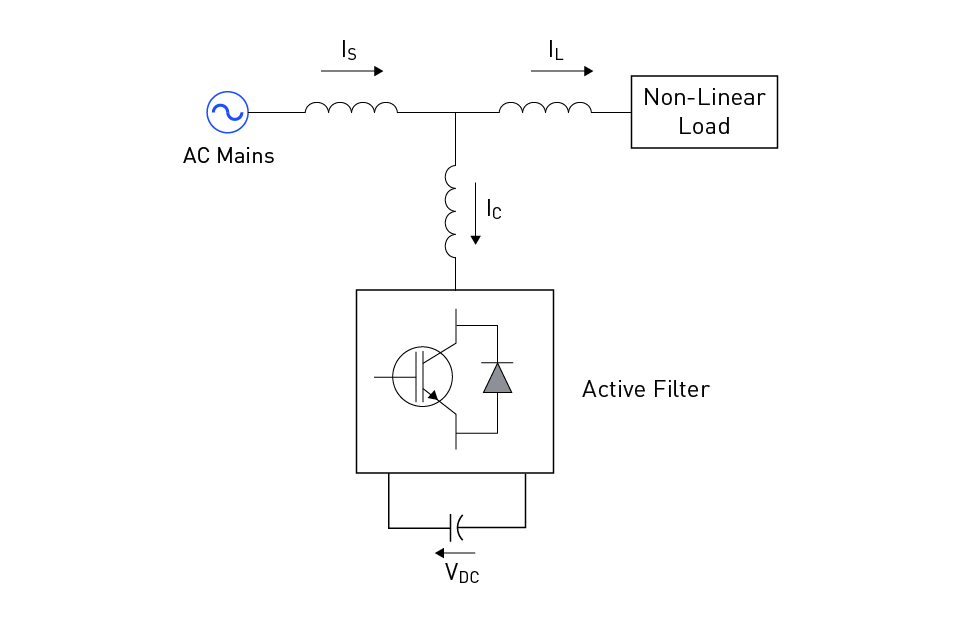
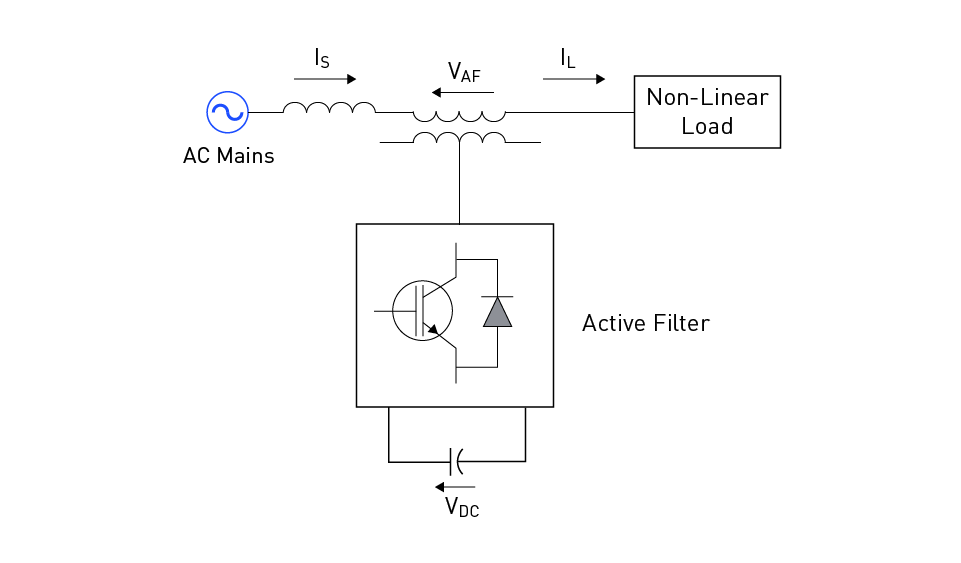
Power electronics called active filters produce harmonic currents that are opposite in phase but equal in magnitude to the harmonic currents produced by the load. This mitigates the harmonic currents' effects on the power system by acting as a countermeasure and effectively canceling them out. The two primary categories of active filters are:
Shunt active filters: In figure 5, the load and shunt active filters are connected in parallel. To remove harmonic distortion from the power system, they measure the harmonic currents created by the load and produce counteracting currents that are injected into the power system.

Figure 5: Shunt active power filter
Series active filters: In figure 6, the load is connected in series with active filters. The voltage distortion is efficiently eliminated by measuring the voltage harmonics at the load terminals and producing counteracting voltages that are injected into the power supply.

Figure 6: Series active power filter
Advantages of active filters:
- Flexible and adaptive harmonic compensation
- The capacity to account for a variety of harmonic frequencies
- Can control voltage and enhance power factor
Drawbacks of active filters:
- Higher cost due to the use of power electronic components and control systems
- They are less trustworthy than passive filters since they rely on active parts and control algorithms
Power Factor Correction
Power systems employ the power factor as a key parameter to determine how well electrical power is converted into productive work. The angle between the apparent power (measured in volt-amperes, VA), and the true power (measured in watts, W), is what is known as the apparent power angle. A power factor of 1 indicates perfect conversion efficiency, with values ranging from -1 to 1.
Importance of Power Factor Correction
Power factor correction (PFC) is essential for several reasons:
To improve system efficiency: The power system is not effectively converting electrical power to useful work if the power factor is low. As a result, energy prices rise and utility grid usage increases.
To reduce voltage drops and losses: A low power factor results in more current flowing through the system, which increases voltage drops and losses in power lines and transformers.
To increase system capacity: The capacity of the power system can be effectively utilized, increasing its ability to manage higher loads without the need for expensive improvements.
To comply with utility regulations: Customers with low power factors frequently face penalties from utilities because they contribute to higher system losses and grid demand.
Power Factor Correction Techniques
There are many ways to fix the power factor, including passive, active, and hybrid techniques:
Passive Power Factor Correction: Capacitors or inductors coupled in parallel or series with the load are used in passive PFC. These reactive components balance out the load's reactive power, thus, raising the power factor. Although passive PFC is straightforward, dependable, and economical, it might not be enough for systems with complicated or variable loads.
Active Power Factor Correction: In order to produce reactive power that offsets the load's reactive power demand, active PFC uses power electronic components like inverters or converters. Compared to passive PFC, this technique provides more accurate and flexible power factor correction. Additionally, active PFC can lessen voltage sag and adjust harmonic distortion. Due to the usage of control systems and power electronic components, it is more complicated and costly.
Hybrid Power Factor Correction: To capitalize on each method's strengths, hybrid PFC blends passive and active methods. By combining the adaptability and improved performance of active PFC with the dependability and cost-effectiveness of passive PFC, this technique can achieve both goals. Power factor correction and harmonic mitigation are both advantages of hybrid PFC for systems with fluctuating loads.


直接登录
创建新帐号