Isolation Performance
Maximum Transient Isolation Voltage
It is essential to comprehend the isolation parameters when developing or assessing isolated systems. "Maximum Transient Isolation Voltage" is one of these crucial characteristics, and it's important for maintaining the dependability and security of electronic systems.
The maximum transient voltage that an isolation barrier can sustain for up to 60 seconds without breaking down is known as the maximum transient isolation voltage. This parameter is critical for applications (e.g., industrial environments, power grids, systems susceptible to electrostatic discharge) where voltage spikes are frequent.
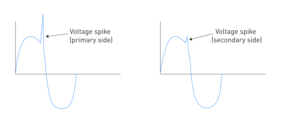
Figure 1: Transient Suppression of an Isolation Transformer
The key aspects of maximum transient isolation voltage are listed below:
Transient Voltage Characteristics: Transient voltages are usually short-lived, sharp spikes in voltage that happen within a circuit. These may be brought on by abrupt changes in the electrical environment, lightning strikes, load variations, switching events, or ESD.
Isolation Barrier Stress: The isolation barrier may be severely stressed by transient voltages. The maximum voltage spike that the isolator can withstand without running the danger of dielectric breakdown or other types of failure is indicated by the Maximum Transient Isolation Voltage rating.
Safety Implications: The system's safety is closely related to its capacity to tolerate high transient voltages. Dangerous circumstances could arise from an isolation barrier breakdown, such as the possibility of electric shock or the failure of vital system components.
Design Considerations: Engineers must choose isolators with the proper Maximum Transient Isolation Voltage rating and take into account the normal transient voltage levels that the system may experience when building isolated systems. This guarantees that, in these circumstances, the isolation doesn't break down.
Testing and Standards: A number of standards, such as IEC 61010-1 or UL 1577, which specify the procedures and requirements for such tests, serve as a guide for testing the maximum transient isolation voltage. These guidelines guarantee consistency in the testing process and offer a standard by which to compare various isolators.
Reliability Over Time: It is crucial to remember that the isolation barrier may gradually deteriorate with repeated exposure to transients close to the maximum rating. It is therefore wise to choose an isolator whose transient voltage rating is greater than the system's maximum anticipated spike.
Isolation Withstand Voltage
The Isolation Withstand Voltage is a fundamental parameter in the field of electrical isolation. It is essential for guaranteeing the functionality and safety of electrical equipment, especially in settings where high voltages are present.
The root mean square (rms) value of the AC voltage that can be applied across an isolation barrier for up to 60 seconds without resulting in a breakdown is known as isolation withstand voltage, or 'VIOW' or 'VISO' for short. This parameter relates to the continuous or steady-state voltage that the isolator can safely handle; transient spikes are addressed by the Maximum Transient Isolation Voltage.
The key elements of isolation withstand voltage are listed below:
Continuous Voltage Endurance: The resist voltage is concerned with the isolation barrier's capacity to tolerate continuous or extended voltages, as opposed to transient voltages, which are momentary in nature. In applications where the isolator is subjected to high voltage on a constant basis, this feature is essential.
Safety Margin: A safety margin above the typical operating voltage is frequently included in the specified withstand voltage. By ensuring that the isolator can withstand unforeseen voltage spikes, this buffer adds another degree of security.
Barrier Integrity: The isolation withstand voltage rating's principal function is to demonstrate the isolation barrier's resilience. A higher rating denotes a more robust barrier capable of averting failures and electrical arcs while guaranteeing long-term dependability.
Standards and Testing: International standards like IEC, IEEE, and UL regulate testing for withstand voltage, just like they do for other isolation characteristics. To achieve uniform and trustworthy measurements, these standards outline the parameters for the tests, including duration and methodology.
Design Implications: Engineers must choose components with an isolation-withstand voltage rating suitable for the voltage environment of the application when developing an isolated system. This entails being aware of the highest voltage levels that the system is capable of experiencing in both fault and normal circumstances.
Impact on Insulation Materials: The kind and caliber of insulation materials employed in the isolator have an impact on its capacity to sustain high voltages over time. The performance of the isolator is greatly influenced by variables such as ambient conditions, dielectric strength, and material deterioration over time.
Relation to Working Voltage: Although they are connected, the working voltage—the voltage that the device is intended to function under on a regular basis—and the isolation withstand voltage are different. Usually higher than the working voltage, the withstand voltage provides a safety net against unanticipated voltage pressures.
Maximum Surge Isolation Voltage
In the context of electrical isolation, the Maximum Surge Isolation Voltage is an essential characteristic, particularly in settings where electrical systems are exposed to high-energy transients. This parameter shows how well an isolator can tolerate surge voltages, which are usually stronger and last longer than transient voltages.
The maximum voltage that an isolation barrier can sustain for a brief period of time without failing is known as the maximum surge isolation voltage, or simply "surge voltage." An isolator claiming a specific VISOM must pass the surge test at a peak voltage of 1.3 times VISOM for basic isolation and 1.6 times VISOM for reinforced isolation, as specified by IEC 60747-5-5 and VDE 0884-11. Typically, switching surges in power systems, lightning strikes, and failures in electrical networks are the causes of surge voltages.
The importance and implications are listed below:
Protection Against High-Energy Events: The resist voltage is concerned with the isolation barrier's capacity to tolerate continuous or extended voltages, as opposed to transient voltages, which are momentary in nature. In applications where the isolator is subjected to high voltage on a constant basis, this feature is essential.
Safety and Reliability: A safety margin above the typical operating voltage is frequently included in the specified withstand voltage. By ensuring that the isolator can withstand unforeseen voltage spikes, this buffer adds another degree of security.
Standardized Testing and Ratings: The isolation withstand voltage rating's principal function is to demonstrate the isolation barrier's resilience. A higher rating denotes a more robust barrier capable of averting failures and electrical arcs while guaranteeing long-term dependability.
System Design Considerations: International standards like IEC, IEEE, and UL regulate testing for withstand voltage, just like they do for other isolation characteristics. To achieve uniform and trustworthy measurements, these standards outline the parameters for the tests, including duration and methodology.
Differences from Transient Voltages: Engineers must choose components with an isolation-withstand voltage rating suitable for the voltage environment of the application when developing an isolated system. This entails being aware of the highest voltage levels that the system is capable of experiencing in both fault and normal circumstances.
Material and Construction Factors: The kind and caliber of insulation materials employed in the isolator have an impact on its capacity to sustain high voltages over time. The performance of the isolator is greatly influenced by variables such as ambient conditions, dielectric strength, and material deterioration over time.
Application in Harsh Environments: Although they are connected, the working voltage—the voltage that the device is intended to function under on a regular basis—and the isolation withstand voltage are different. Usually higher than the working voltage, the withstand voltage provides a safety net against unanticipated voltage pressures.
Maximum Repetitive Peak Voltage
In the context of electrical isolation, the Maximum Surge Isolation Voltage is an essential characteristic, particularly in settings where electrical systems are exposed to high-energy transients. This parameter shows how well an isolator can tolerate surge voltages, which are usually stronger and last longer than transient voltages.
The maximum voltage that an isolation barrier can sustain for a brief period of time without failing is known as the maximum surge isolation voltage, or simply "surge voltage." An isolator claiming a specific VISOM must pass the surge test at a peak voltage of 1.3 times VISOM for basic isolation and 1.6 times VISOM for reinforced isolation, as specified by IEC 60747-5-5 and VDE 0884-11. Typically, switching surges in power systems, lightning strikes, and failures in electrical networks are the causes of surge voltages.
The significance and applications are listed below:
Stress Endurance Over Time: The isolation materials may experience wear and breakdown over time due to cumulative stress caused by the recurrent nature of these high voltages. As a result, the isolation barrier's long-term resilience to repeated voltage stressors is gauged by VIOPM rating.
Application in Switching Environments: Systems that frequently switch, like power converters, inverters, or pulse-width-modulated (PWM) controllers, should pay special attention to this parameter. The isolator in these applications is frequently subjected to high-voltage peaks.
Safety and Reliability: Because the isolator is less likely to fail early from voltage-induced stress, systems built to operate within the Maximum Repetitive Peak Voltage restrictions offer a greater level of safety and reliability.
Design Considerations: The VIOPM should be taken into account along with other characteristics such as the working voltage and transient voltage capabilities when constructing an isolation system. It is important to choose an isolator that can easily withstand the peak voltages anticipated for the particular application.
Material and Construction Impact: The quality and kind of materials utilized in the isolator, as well as the isolation barrier's design, affect the device's capacity to tolerate repeated peak voltages. Dielectric strength, material fatigue characteristics, and thermal stability are a few examples of important factors.
Testing and Standards Compliance: A number of electrical standards specify how tests should be conducted in order to ascertain the VIOPM. To ensure that the isolator satisfies the necessary performance requirements over its anticipated lifetime, these tests replicate recurrent high-voltage circumstances.
Consideration of Application-Specific Factors: Because of the continuous exposure to high-voltage peaks at irregular intervals, the VIOPM becomes a crucial parameter in applications using variable-frequency drives (VFDs) or other high-frequency operating environments.
Working Voltage
A significant component in electrical isolation is the working voltage, which determines the highest continuous voltage that may be given over the isolation barrier while the system is functioning normally. The working voltage parameter determines this voltage. This parameter is required in order to ensure that isolated systems can be effectively configured and operated in a secure manner.
The maximum rms, or corresponding DC voltage, that an isolation barrier is able to safely endure on a continuous basis is referred to as the working voltage, or "VIOWM" When determining whether or not an isolator is suitable for a particular application, it is essential to take into account this parameter, which is distinct from transient or surge voltage characteristics, which are concerned with short-term voltage spikes.
The significance in isolation design is listed below:
Continuous Voltage Handling: The working voltage is a representation of the steady-state operating situation, as opposed to transient or surge voltages. It is essential to take this into account in order to guarantee that the isolator can operate as intended under typical electrical circumstances.
Safety Margin: To provide a buffer against unanticipated voltage rises, the working voltage is typically set with a safety margin below the isolation withstand voltage. This buffer adds to the isolator's overall dependability and safety.
Material and Design Considerations: The dielectric strength of the insulation materials used, the physical distance between conductive parts (creepage and clearance), and the isolation barrier's overall design all have an impact on an isolator's capacity to withstand its designated working voltage.
Application Relevance: The voltage levels that are often present in the application must be taken into consideration while selecting the working voltage. For example, isolators in low-voltage consumer electronics may require a lower working voltage than isolators used in industrial control systems.
Standards and Regulations Compliance: Testing protocols and requirements for working voltage are defined by a number of international standards, including IEC and UL. Adherence to these guidelines guarantees that the isolator is appropriate for the purpose for which it was designed.
Long-Term Reliability: The isolator's long-term dependability may be impacted by constant exposure to voltages close to the maximum working voltage. Consequently, it is best to choose an isolator whose working voltage rating is greater than the highest continuous voltage that the application is likely to require.
Thermal Considerations: The isolator may get heated as a result of constant voltage application. The isolator's thermal stability must be taken into consideration in the working voltage rating to guarantee that it can function efficiently without overheating.
Timing Parameters
Timing factors play a critical role in digital isolation, impacting isolation solutions' overall performance and applicability in many scenarios. The three most important timing parameters—data rate, propagation delay, and propagation delay skew, are covered in this section.
Data Rate
The fastest possible speed at which data can pass through the isolator is referred to as the data rate. In situations where high-speed communication is crucial, it is an important parameter.
Factors Affecting Data Rate: The technology (optical, magnetic, or capacitive) of the isolator, the state of its internal parts, and the working environment all have an impact on data rate. Cleaner signal conditions and shorter distances are generally linked to higher data speeds.
Propagation Delay
The amount of time it takes for a signal to travel from the input to the output of an isolator is known as the propagation delay. In synchronous systems, when timing accuracy is critical, it is an essential component.
Factors Impacting Propagation Delay: The internal circuitry and materials utilized in the isolator determine the delay. In general, propagation delays are less for optical isolators than for capacitive or magnetic ones.
Propagation Delay Skew
The difference in propagation delay between multiple units of the same type or between different channels of the same isolator is known as the propagation delay skew. When several channels require time consistency, it becomes important in parallel data systems.
Minimizing Propagation Delay Skew: Manufacturers frequently impose stringent controls on component tolerances and operating parameters to guarantee consistency. Skew can also be decreased by employing balanced circuit layouts and matching trace lengths as design strategies.
Impact and Considerations in System Design
System Synchronization: Timing parameters are essential for preserving system synchronization, particularly in applications involving high-speed digital processing and transmission.
Tradeoffs: High data rate, short propagation latency, and minimal skew are trade-offs that designers frequently have to make. Achieving the ideal isolator requires striking a balance between these variables in accordance with the particular needs of the application.
Environmental Influence: Timing parameters can be impacted by external influences like temperature changes and electromagnetic interference. Therefore, careful design considerations are necessary to minimize these impacts.
Common-Mode Transient Immunity (CMTI)
Common-Mode Transient Immunity (CMTI) plays a crucial role in digital isolation, especially in environments with significant electrical noise and transient disturbances. You can test an isolator's ability to keep signals pure and work reliably in rough electrical environments by measuring its common-mode transient noise rejection.
The CMTI is mostly expressed in kilovolts per microsecond (kV/μs). It shows how well the isolator can handle sudden changes in the potential difference between two grounds, which is called common mode. Common-mode voltage is the voltage that occurs at the same time and in sync on both input and output lines with respect to the ground.
Importance of CMTI in Isolation
Noise Rejection: High CMTI values are a sign of strong immunity to external noise transients. This is especially important in industrial and automotive environments, where equipment is often exposed to significant and sudden changes in voltage.
Signal Integrity: Ensuring signal integrity is crucial when using isolators in data communication or signal processing applications, as it helps to maintain the accuracy and reliability of the transmitted data. With a high CMTI, data can be transferred across the isolation barrier without any worries about corruption from transient noises.
Reliability in Harsh Environments: In applications where the electrical environment can be extremely noisy, reliability in harsh environments is crucial. Isolators that have high CMTI ratings are the preferred choice in these settings to guarantee a dependable and consistent operation.
Measurement and Standards
Testing Procedures: The measurement of CMTI is conducted in a controlled environment, where an isolator is subjected to a common-mode transient. The assessment focuses on the isolator's capability to preserve signal integrity.
Compliance with Standards: It is essential to adhere to international standards, such as IEC or IEEE specifications, when testing CMTI. These standards help maintain consistency in testing across various devices and applications.
Impact of Design Factors
Internal Circuitry: When it comes to the isolator, the internal circuitry plays a crucial role in determining its CMTI rating. Factors such as propagation delay and internal filtering have a direct impact on its performance.
Material Properties: The properties of the materials used in the construction of the isolation barrier can have an impact on the CMTI. Materials that possess a higher dielectric strength typically result in improved transient immunity.
Applications and Considerations
Digital Interfaces: For high-speed digital interfaces, CMTI is a crucial factor in guaranteeing flawless data transmission.
Power Management: When it comes to power management systems, particularly those that involve switching operations, isolators with high CMTI are the preferred choice to effectively handle the rapid voltage changes.
Power Consumption
Key Aspects of Power Consumption in Digital Isolation
Static and Dynamic Power Consumption: Power consumption in digital isolators can be categorized into two types: static (quiescent) and dynamic (active) consumption. Static power represents the energy consumption of the device when it is not actively switching, whereas dynamic power accounts for the energy used during signal transmission.
Influencing Factors: A number of factors, such as the frequency of operation, the capacitive load in the circuit, and the specific technology used (capacitive, inductive, or optical), affect how much power digital isolators use. For example, capacitive isolators generally have lower power consumption when compared to inductive isolators.
Impact on System Design
Battery-Powered and Portable Applications: For battery-powered and portable applications, it is crucial to select a digital isolator with low power consumption. This is particularly important in devices like portable and wearable devices, where battery life is a top priority.
Thermal Management: Dealing with higher power consumption requires implementing efficient thermal management solutions in the system design to handle the increased heat generation.
System Efficiency: The power consumption of the isolation component can have a significant impact on the system's overall efficiency, particularly in applications that call for energy conservation.
Strategies for Reducing Power Consumption
Optimization of Operating Frequency: Lowering the operating frequency can help minimize dynamic power consumption, but it's important to consider its potential impact on the data rate.
Use of Low-Power Technologies: Progress in semiconductor technologies has facilitated the creation of digital isolators that are more energy-efficient, thanks to the development of low-power ICs.
Intelligent Power Management: Implementing intelligent power management strategies, such as power-down modes or dynamic adjustment of power based on load conditions, can greatly reduce overall power usage.
Package
Creepage and Clearance
Creepage is the term used to describe the shortest distance along the surface of the insulation between two conductive parts or between a conductive part and the equipment's bounding surface. Clearance refers to the shortest distance between two conductive parts, typically measured through air. Both parameters play a vital role in preventing electrical arcing and ensuring the isolator's safety.
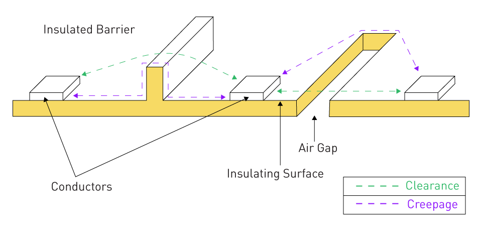
Figure 2: Creepage and Clearance
Determining Factors: The voltage at play, the characteristics of the materials involved, and the surrounding environmental conditions all have an impact on the creepage and clearance distances required. These distances expand as the voltage rises to avoid any potential breakdown of the dielectric.
Design Implications: The requirement to maintain adequate creepage and clearance distances can have an impact on the physical size of the digital isolator. Striking a delicate balance between size reduction and electrical safety is often required.
Comparative Tracking Index (CTI)
The comparative tracking index measures the resistance of the material in an isolator to electrical breakdown under high-voltage, low-current conditions. It plays a crucial role in assessing the quality and appropriateness of materials for insulation purposes.
CTI Value and Selection: Materials that possess higher CTI values demonstrate superior resistance to electrical breakdown. Choosing the right material with a suitable CTI value is crucial, particularly in environments that have high humidity or contaminants.
Impact on Design: The CTI has a significant influence on the package design of the digital isolator, especially when it comes to spacing requirements. With higher CTI materials, it becomes possible to achieve more compact designs while maintaining the same level of safety for the working voltage.


直接登录
创建新帐号