Principles of Galvanic Isolation
Galvanic isolation, an essential idea in electrical engineering, is necessary to guarantee the security, integrity, and appropriate operation of electronic systems. Transferring power and/or data between two circuits while stopping the flow of dangerous DC or erratic AC transient currents is referred to as this. Galvanic isolation's main goal is to cut off dangerous currents' electrical paths and isolate the various components of the system from one another.
Among the fundamentals of galvanic isolation are:
Electrical Separation: Establishing a complete electrical separation between two circuits is the fundamental component of galvanic isolation. This separation is essential to preventing electric shocks to users and systems, especially in high-voltage situations.
Signal Transfer without Direct Connection: Signal transfer between the isolated components is frequently required, notwithstanding their isolation. Direct electrical conduction is not necessary for this transfer because it uses electromagnetic, capacitive, or optical techniques.
Energy Transfer: Energy transfer over the isolation barrier is a possible aspect of galvanic isolation, in addition to signal transfer. In power supply applications, where it's essential to isolate the input from the output for safety concerns, this is usually accomplished using transformers.
Breaking Ground Loops: Galvanic isolation can effectively break ground loops, which can cause unwanted noise and interference in electronic systems. These loops are broken by electrically isolating specific portions of a circuit, which solves the related issues.
Protection against Voltage Surges and Transients: Galvanic isolation offers a number of important benefits, including the ability to shield delicate electronic components from voltage spikes and transients. Galvanic isolation serves as a protective measure against these unplanned, abrupt spikes in voltage, which have the potential to be hazardous.
Implementation Methods
There are several ways to establish galvanic isolation:
Transformers: Magnetic coupling is the process by which energy is transferred between two windings that are physically apart but magnetically coupled. Transformers are mostly used for power and signal isolation.

Figure 1: Using Transformer for Galvanic Isolation
Optocouplers: These parts transfer signals over an isolation barrier using light. When an electrical signal is provided, an LED on one side generates light, which is then recognized by a photodetector on the other side, therefore conveying the signal without the need for direct electrical contact.
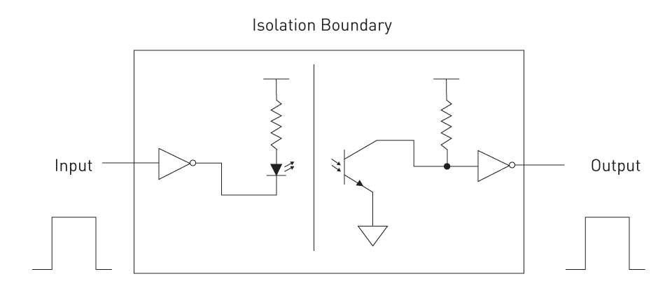
Figure 2: Optocoupler Galvanic Isolation
Capacitive Isolators: These gadgets transmit signals via electric fields. Again, without direct electrical connectivity, they are constructed with capacitive parts that enable signal transfer through variations in electric fields.
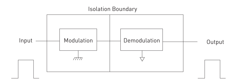
Figure 3: Capacitive Galvanic Isolation
In electrical and electronic engineering, galvanic isolation is an essential approach that protects against ground loop issues, noise interference, and electrical shocks. Its implementation is essential to producing high-performing, dependable, and safe electronic devices and systems because it guarantees that various components can safely and effectively interact without being electrically coupled.
Optoisolation: How Light is Used as an Isolation Medium
Using light as the medium, optoisolation—also referred to as optical isolation or optocoupling—is a technique for transferring electrical impulses between two isolated circuits. By guaranteeing that there is no direct electrical connection between the input and output, this technique offers galvanic isolation, shielding users' devices from unregulated and potentially dangerous voltage and noise.
Fundamentals of Optoisolation
Components of an Optoisolator: A light emitter and a light receiver are the two main parts of an optoisolator. Light-emitting diodes (LEDs) are commonly used as the emitter, and photodiodes, phototransistors, or photodarlingtons are commonly used as the receiver. To avoid influence from outside light, these components are kept inside a sealed container. An infrared light-emitting diode (IR LED) serves as the transmitter in a somewhat modified configuration, while a phototransistor serves as the receiver.
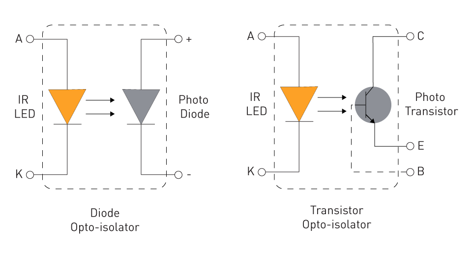
Figure 4: Types of Optoisolators
Operation Mechanism: The LED emits light in response to the strength of an applied electrical signal. The photoreceiver on the other side of the isolation barrier detects this light as it passes through. After that, the light is transformed back into an electrical signal by the receiver, which is electrically insulated from the input signal but resembles it.
Isolation and Safety: The main benefit of optoisolation is its strong galvanic isolation capabilities. Voltage spikes or surges from one side of the circuit impacting the other do not pose a risk of electrical shock or damage because light is the only medium that can get over the isolation barrier.
Applications: In many different situations where isolation is essential, optoisolators are employed extensively. Microcontrollers are frequently used for high-voltage system interfaces, data communication line isolation, and power supply circuit isolation. They are particularly common in consumer electronics, medical devices, and industrial control systems where signal integrity and safety are crucial.
Advantages of Optoisolation
Electrical Noise Immunity: Optoisolators are very good at keeping electrical noise from passing through the isolation barrier. They are therefore perfect for use in high-level electromagnetic interference (EMI) situations.
Wide Bandwidth: Due to their high speed of data transfer, optoisolators of today are well suited for a wide range of digital applications that demand quick signal transmission.
Compact and Cost-Effective: Compared to other isolation techniques like transformers, optoisolators are comparatively small and affordable.
Limitations of Optoisolation
Linear Response: Optoisolators are great for digital signals, but because of their non-linear responses at specific frequencies and light intensities, their application in isolating analog signals may be restricted.
Temperature Sensitivity: Under extreme circumstances, the effectiveness of LED light emission and photodetector reactions may differ depending on the temperature.
Aging Effects: Over time, LED output may deteriorate, affecting optoisolators' long-term dependability.
Magnetic Coupling: Role of Transformers and Inductors in Isolation
In electrical engineering, magnetic coupling is a basic technique for achieving isolation between various components of an electronic system. The main method is to employ magnetic fields to transport energy and signals across an isolation barrier using transformers and inductors. In a variety of applications, this technique is essential for guaranteeing power management, safety, and signal integrity.
Transformers in Isolation
Principle of Operation: Transformers use electromagnetic induction to achieve isolation. Two windings, the primary and secondary, are usually coiled around a magnetic core to produce a transformer. The main winding produces a magnetic field that causes a voltage in the secondary winding when an alternating current (AC) passes through it. Without a direct electrical connection, power or signals can be transferred between circuits using this induced voltage.
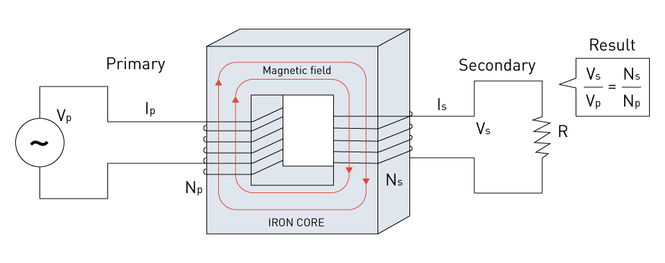
Figure 5: Transformer
Galvanic Isolation: The capacity of transformers to produce galvanic isolation is one of their main benefits. Transformers effectively stop direct current (DC) and any related faults or surges from flowing from one side to the other since the primary and secondary windings are not electrically coupled. This ensures safety and shields delicate components.
Applications: Transformers separate the high-voltage side from the low-voltage side in power supplies, especially switching power supplies and AC adapters. They are also utilized for power transfer and signal separation in industrial control circuits, medical equipment, and audio systems.
Inductors in Isolation
Role in Signal Isolation: An inductor, also known as a coil or choke, can help isolate signals at high frequencies, even if transformers are best suited for AC transmissions. As a filter and a kind of isolation, an inductor in a circuit can block high-frequency impulses while letting low-frequency or DC signals through.
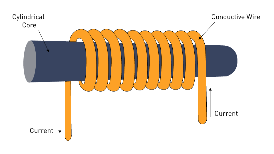
Figure 6: Simple Inductor
Common-Mode Chokes: Unwanted common mode noise, or signals that occur simultaneously and in phase on two lines of a circuit, is filtered out by a particular kind of inductor called a common mode choke. In order to lessen electromagnetic interference (EMI) in data and power lines, they are crucial.

Figure 7: Common-Mode Choke
Key Considerations in Magnetic Coupling
Frequency Response: The behavior of transformers and inductors varies with frequency. The precise frequency range of the application must be taken into account while designing these parts, including the core material and winding requirements.
Size and Efficiency: Inductors and transformers' physical dimensions play a crucial role, particularly in small, portable systems. Design and material advancements have produced smaller, more effective components.
Power Handling Capability: It is essential that transformers and inductors be able to manage power without saturation or overheating. This is especially crucial for power applications that require large currents.
Isolation Voltage Rating: The amount of isolation that transformers and inductors can offer is based on their voltage ratings. To guarantee safety and dependability, higher voltage ratings are needed for applications involving high voltages.
Capacitive Coupling: The Idea Behind Using Capacitors for Isolation
Capacitive coupling is an isolation technique that transfers signals across an isolation barrier by means of the electric field produced by capacitors. This method is very useful for applications that need to move data quickly and take up little physical space. By definition, capacitive coupling presents a distinct set of features and benefits in contrast to other isolation techniques like optical (optocouplers) or magnetic (transformers) isolation.
Principles of Capacitive Isolation
Principle of Operation: The basic idea behind capacitive coupling is that a capacitor is created when two conducting plates, also known as electrodes, are spaced apart by a dielectric substance. An electric field is created across the dielectric when a voltage is applied to one plate, which causes a voltage to be induced on the other plate. Without making direct electrical contact, signal information is sent across the isolation barrier using this phenomenon.
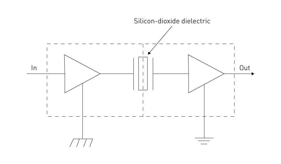
Figure 8: Capacitive Isolator
Signal Transfer: Capacitive isolators are constructed with incorporated capacitive elements into a semiconductor substrate to achieve signal isolation. High-speed digital signals can pass across the isolation barrier thanks to these capacitors' quick charging and discharging in response to input signal changes.
Galvanic Isolation: Capacitive coupling offers galvanic isolation between input and output, just like other isolation methods. By ensuring that there isn't a direct current channel between the two sides of the isolator, this protects against ground potential differences, high voltage transients, and the transmission of DC voltages.
Applications of Capacitive Isolation
High-Speed Data Communications: Because capacitive isolators can carry data quickly, they are perfect for use in serial data protocols and other communication interfaces like Ethernet and USB.
Compact Electronic Systems: Capacitive isolators are ideally suited for usage in compact electronic systems where space is at a premium because of their tiny size and incorporation into semiconductor technology.
Advantages of Capacitive Coupling
High-Speed Performance: Capacitive isolators are suited for high-speed digital applications because they can send data at a faster rate than inductive or optical isolators.
Low Power Consumption: In battery-powered and energy-sensitive applications, these isolators usually have a lower power consumption.
Reduced EMI: The lack of magnetic fields in capacitive coupling lessens the possibility of electromagnetic interference (EMI), a crucial factor in delicate electronic systems.
Small Size and Integration: Capacitive isolators enable more compact circuit designs since they are small and simple to integrate into semiconductor processes. This functionality is especially useful for situations where there is little space, such as small industrial systems and mobile devices.
Lower Propagation Delay: Capacitive isolators' high speed results in reduced propagation delays, which speed up data transfer and control system response times.
Stability Over a Wide Frequency Range: Capacitive coupling is perfect for a wide range of digital communication applications because it keeps signals stable over a large frequency spectrum.
Limitations of Capacitive Coupling
Limited Insulation Resistance: In applications where very high insulation resistance is required, the dielectric in capacitors may permit some leakage current.
Sensitivity to External Factors: The performance and dependability of capacitive isolators can be impacted by external conditions such as temperature and humidity.
Limited Voltage Isolation Capability: Although capacitive coupling works well for signal isolation, it might not be the best option for applications that need very high voltage isolation levels.
Dielectric Breakdown Concerns: The capacitor's dielectric material may degrade at high voltages, jeopardizing isolation and possibly resulting in failure.
Variation with Frequency: To guarantee constant performance, the capacitive coupling efficiency may vary depending on the signal frequency. This makes careful design consideration necessary.
Challenges in Scaling: It gets harder to scale capacitive isolation solutions while preserving their fundamental benefits when systems require larger isolation voltages and power levels.
Giant Magneto-Resistance (GMR) Isolation
A complex method used in digital isolation to guarantee signal integrity and isolation in high-speed data transfer applications is called giant magneto-resistance (GMR) isolation. The GMR effect, a quantum mechanical phenomenon where certain materials' electrical resistance increases dramatically in reaction to magnetic fields, provides the basis for GMR isolation. The foundations, benefits, and uses of GMR isolation are covered in detail in this section.
Principles of GMR Isolation
GMR Effect: First identified in multilayered thin films consisting of alternating ferromagnetic and non-magnetic layers, the GMR effect was discovered in the late 1980s. The alignment of the electron spins in these layers varies when subjected to a magnetic field, resulting in a notable variance in electrical resistance. GMR isolators use this modification to send data through an isolation barrier.
Signal Transmission: In GMR isolators, data is sent by creating magnetic fields that match the data signal. Digital isolation is achieved by changing the resistance of the GMR sensor, which is subsequently transformed back into an electrical signal on the isolated side by these magnetic fields.
Advantages of GMR Isolation
High-Speed Data Transfer: GMR isolators are ideal for applications where quick data transmission is essential, including high-speed communication interfaces, since they provide high-speed operation with extremely minimal pulse width distortion and propagation delay skew.
Excellent Linearity: For precise data conversion and processing, GMR isolators offer greater linearity in signal transmission.
Miniaturization Potential: These isolators may be made in very small sizes, which is advantageous for downsized electronic devices because of the microscopic scale of the GMR effect.
Low Power Consumption: GMR isolators generally use less power than more conventional isolation techniques, which is in line with the objectives of energy-efficient design.
Temperature Tolerance: GMR isolators operate consistently in a broad range of temperatures. Moreover, GMR isolators show stability in the face of repeated temperature cycles without experiencing any structural deterioration.
Applications and Use Cases
High-Speed Communication: For applications like modern networking and communications systems that demand high data rates, GMR isolators are perfect.
Precision Sensing: GMR isolators can be used for magnetic field sensing and current measurement, among other precision sensing applications, due to their sensitivity to magnetic fields.
Industrial Automation: GMR isolators are crucial for preserving signal integrity and system dependability in settings where fast data transfer and precise control are required.
Challenges and Considerations
Sensitivity to External Magnetic Fields: Careful shielding and design considerations are required since GMR isolators are susceptible to interference from external magnetic sources.
Fabrication Complexity: Compared to conventional isolation techniques, the production of GMR isolators can be more expensive and complex due to the advanced nanoscale fabrication procedures involved.


直接登录
创建新帐号