Capacitive Coupling
A crucial technique employed in digital isolation; capacitive coupling utilizes the principles of electrical capacitance to convey signals across an isolation barrier.
Fundamental Concepts and Theory
Basic Principle: Operating on the principle of electric fields, capacitive coupling involves two conductive plates separated by a dielectric (non-conductive) material in its simplest form. Together, these plates make a capacitor.
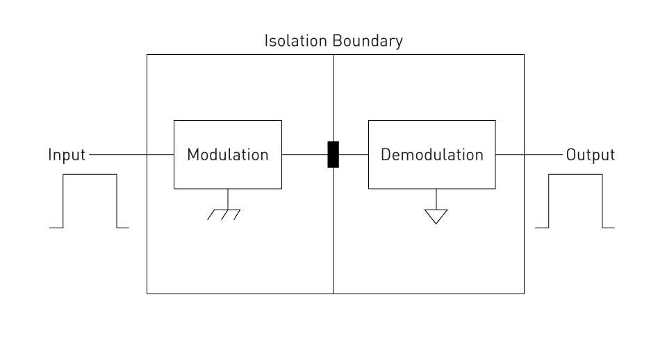
Figure 1: Capacitive Coupilng Concept
Signal Transfer Mechanism: An electric field is produced across the dielectric when a voltage signal is applied to one of the conductive plates (the transmitter side). Inducing a corresponding voltage on the second plate (the receiver side), this field effectively transfers the signal across the isolation barrier without requiring direct electrical contact.
Circuit Implementation: Capacitive coupling is utilized in digital isolators through integrated circuits housing microfabricated capacitor structures. Employing signal modulation techniques like on-off keying, digital signals are encoded across the capacitive barrier.
Impedance Considerations: To reduce signal reflections, source-impedance matching is needed near the isolator. It is necessary for the isolator output impedance to align with the transmission line (trace) impedance.
Advantages and Disadvantages
Advantages
- High-Speed Data Transfer: High data transfer rates allowed by capacitive coupling make it suitable for applications that need fast communication, like high-speed data buses.
- Compact and Integrated Design: Enabling compact and integrated circuit designs, the technology lends itself well to miniaturization.
- Low Power Consumption: In contrast to other isolation methods, capacitive isolators typically consume less power which is advantageous for power-sensitive applications.
- Reliability: Improved reliability and significantly prolonged operational life result from the lack of degradation in component performance, such as LEDs in optocouplers.
Disadvantages
- Susceptibility to External Fields: Potential signal distortion or interference may arise due to the influence of external electric fields, impacting the effectiveness of capacitive coupling.
- Impedance Matching Requirements: Efficient signal transfer relies heavily on proper impedance matching, a critical factor that can complicate circuit design, particularly in mixed-signal environments.
- Reduced Effectiveness at Low Frequencies: The capacitive reactance rises at lower frequencies, which can decrease the signal transfer efficiency across the isolation barrier.
Magnetic Coupling
A fundamental technique utilized to attain electrical isolation while allowing signal transmission is known as magnetic coupling. For transferring signals, it uses the principles of electromagnetic induction.
Fundamental Concepts and Theory
Basic Principle: The foundation of magnetic coupling lies in electromagnetic induction, wherein a magnetic field facilitates the transfer of signals across an isolation barrier. Two main elements, namely a transmitter coil and a receiver coil are involved in this process.
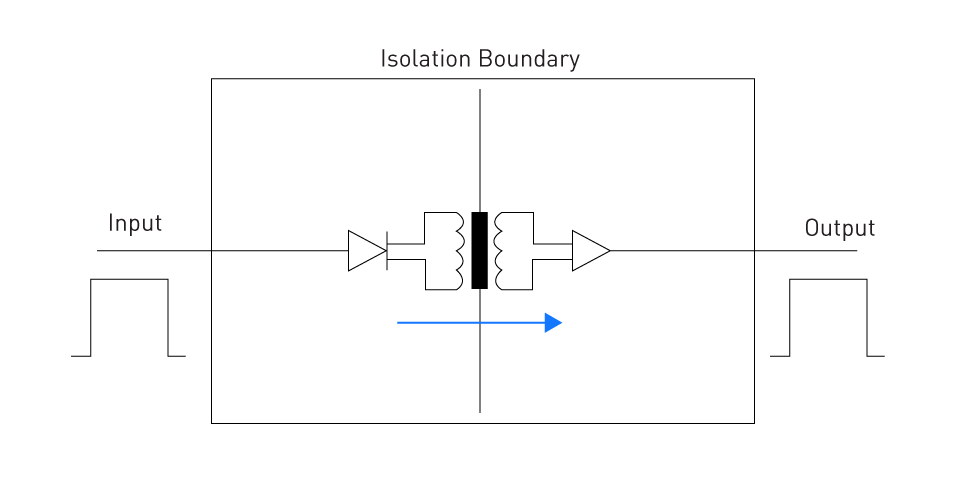
Figure 2: Magnetic Coupling Concept
Signal Transfer Mechanism: A magnetic field in the transmitter coil is created by an electrical current. Crossing the isolation barrier, the magnetic field induces a corresponding current in the receiver coil on the opposite side, effectively transmitting the signal without requiring physical electrical connectivity.
Implementation in Digital Isolators: Achieving magnetic coupling in digital isolators commonly involves incorporating miniature transformers within the isolator package. Designed to function at elevated frequencies, these transformers are well-suited for transmitting digital signals.
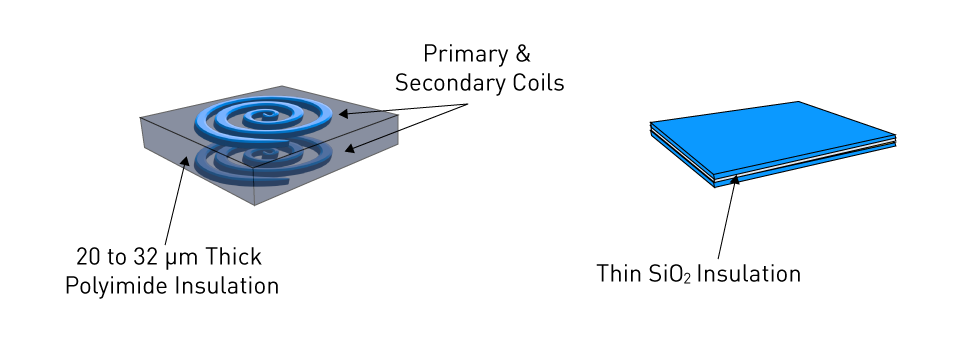
Figure 3: Magnetic Coupler Designs with Different Isolation
Advantages and Disadvantages
Advantages
- High Isolation Voltage: High isolation voltages are provided by magnetic coupling which makes it ideal for applications employing high voltage levels, like power electronics.
- Robustness to External Interference: By offering a more stable signal transfer in a noisy environment, this method is less susceptible to external noise.
- Good Power Transfer Capability: Not only efficient for signal transmission, but magnetic coupling can also transfer power across the isolation barrier, proving useful for energizing isolated circuits.
Disadvantages
- Lower Data Rate: Magnetic coupling typically provides lower data transfer rates as compared to capacitive or optical coupling. However, for high-speed digital applications, this data transfer rate might not be sufficient.
- Potential for Magnetic Saturation: Transformers utilized in magnetic coupling may undergo saturation, particularly when incorporating magnetic components, especially under high current conditions, potentially impacting performance and signal integrity. Conversely, couplers lacking magnetic components do not encounter this issue.
- Complexity in High-Frequency Operation: For high-frequency operation, designing magnetic coupling can present complexity and challenge, necessitating meticulous consideration of transformer core materials and geometry.
Giant Magneto-Resistance (GMR) Coupling
Fundamental Concepts and Theory
In digital isolators, Giant Magneto-Resistance (GMR) coupling is an advanced technology leveraging the GMR effect. Discovered in 1988, this quantum mechanical phenomenon manifests as a pivotal change in electrical resistance due to an external magnetic field. Thin-film structures, comprising alternating layers of ferromagnetic and non-magnetic materials, are used in GMR coupling. Altering the resistance of these layers, the presence of a magnetic field facilitates the conversion of magnetic signals into electrical signals across an isolation barrier. In digital isolators, where electrical isolation is paramount, this process is crucial for data transmission.
Centering on the alignment of electron spins in the ferromagnetic layers, the operational principle of GMR isolators is founded. In the absence of a magnetic field, parallel alignment results in low resistance, whereas under a magnetic field, antiparallel alignment increases resistance. Precisely measuring this change in resistance, it is utilized to transmit digital signals across the isolation barrier, ensuring both data integrity and isolation simultaneously.
Advantages and Disadvantages
Advantages
- High Data Rate Capability: Suitable for applications requiring rapid data transmission, like high-speed communication interfaces, GMR isolators excel in high-speed operation, boasting minimal pulse width distortion and propagation delay skew.
- Low Power Consumption: In contrast to legacy isolation methods, these isolators consume less power making them advantageous for energy-sensitive and battery-operated devices.
- Immunity to External Interference: Among all isolation technologies, GMR isolators stand out with the best EMC footprint, featuring low emissions, susceptibility to EMI, and superior magnetic immunity.
- Compact Size: Supporting the trend towards miniaturization in electronic devices, their small form factor is noteworthy.
- Temperature Stability: Across a wide range of temperatures, the performance of GMR isolators remains stable. Additionally, they exhibit stability even when subjected to multiple thermal cycles, showing no signs of structural degradation.
Disadvantages
- Cost Considerations: Because of their complicated manufacturing process, GMR isolators can be more expensive than conventional isolation methods.
- Manufacturing Precision: To ensure the integrity of the thin-film structures, the production of GMR isolators needs accurate fabrication strategies.
Optical Coupling
In digital isolators, optical coupling, also referred to as optoisolation, is extensively utilized. Using light to attain electrical isolation while enabling signal transfer, optical coupling offers unique benefits in certain applications.
Fundamental Concepts and Theory
Basic Principle: Relying on the transmission of signals through light, optical coupling typically incorporates an LED (Light Emitting Diode) to transmit the signal and a photodetector, like a phototransistor or photodiode, to receive the signal.
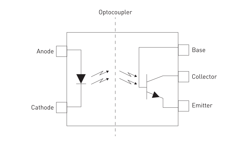
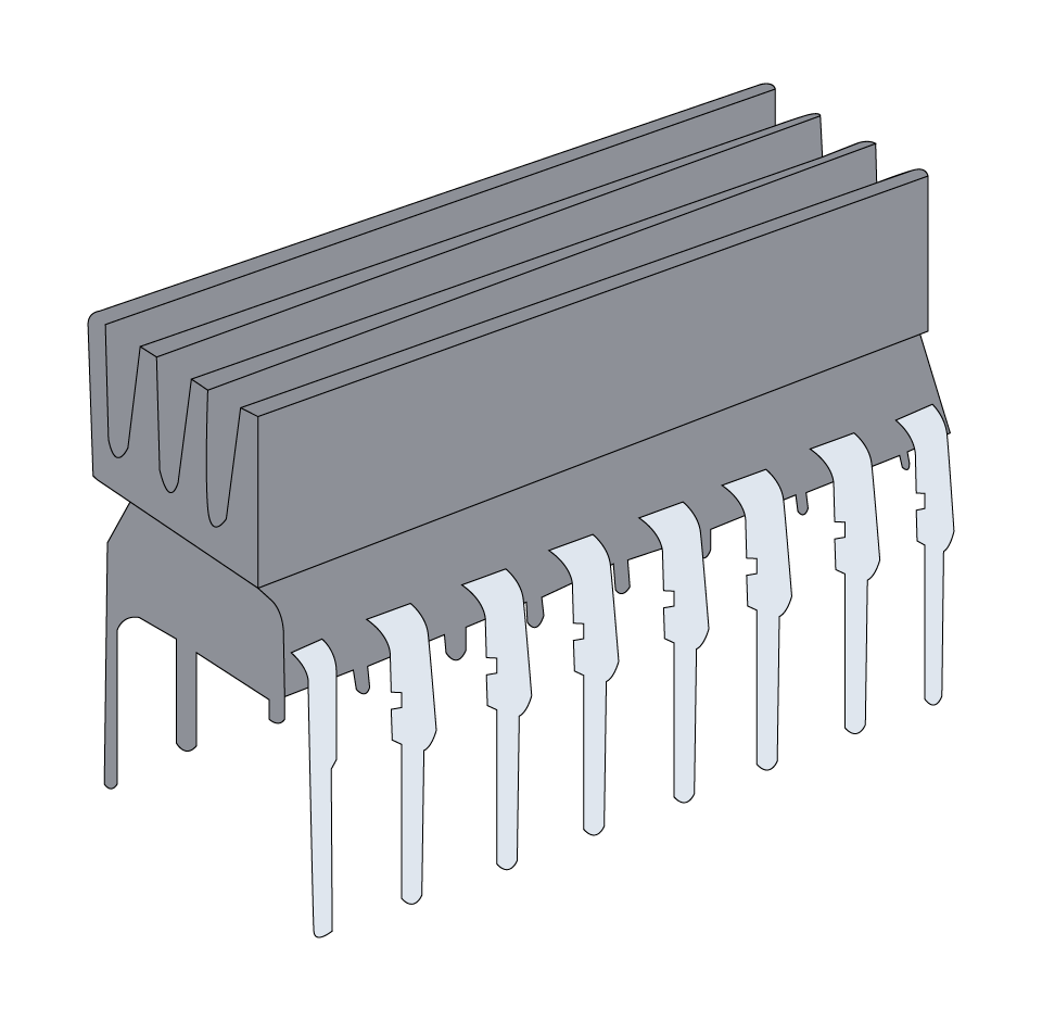
Figure 4: Optocoupler Pinout
Signal Transfer Mechanism: LED emits light proportional to the signal when an electrical signal is applied to it. Traversing the isolation barrier, this light is captured by the photodetector on the receiving side, which subsequently converts it back into an electrical signal, thereby finalizing the isolation process.
Isolation Barrier: Typically constituted of a molding compound through which light travels, the isolation barrier is central to optical coupling. This barrier simultaneously furnishes electrical isolation and permits the passage of optical signals.
Modulation and Demodulation: For the efficient transmission of digital signals, modulation techniques are employed to encode the electrical signal into a format suitable for conveyance by the LED. Upon reception, demodulation converts the light signal back into an electrical form.
Advantages and Disadvantages
Advantages
- High Electrical Isolation: As the isolation barrier is non-conductive and immune to electrical interference, optical isolators offer excellent electrical isolation.
- Immunity to Electromagnetic Interference (EMI): Due to its optical nature, signal transmission inherently exhibits immunity to EMI, rendering optical couplers ideal for environments with high electrical noise levels.
- Safety in High-Voltage Applications: Applications involving high voltages, like power supply units and industrial equipment can benefit from the suitability of optical coupling due to the absence of direct electrical connectivity.
Disadvantages
- Limited Data Rate: Due to the LED and photodetector's comparatively inferior switching characteristics and response time, the data rate of optical isolators is generally lower than that of capacitive or magnetic isolators.
- Component Aging: Changes in performance and a reduction in the isolator’s lifespan can be caused by the degradation of LEDs over time.
- Size Considerations: Optical isolators have the potential to be larger than capacitive or magnetic alternatives.


直接登录
创建新帐号