Introduction to EMC and Its Importance
Electromagnetic compatibility (EC) is of utmost importance when it comes to designing and operating electronic devices, such as digital isolators. Ensuring that a device operates smoothly within its electromagnetic environment without causing any disruptive electromagnetic disturbances is crucial.
Understanding EMC
Definition and Components: EMC consists of three main components: emission, susceptibility, and immunity. Limiting the amount of electromagnetic interference (EMI) a device generates is crucial to ensuring emission control. Concerning the probability of equipment breakdown or malfunction in the presence of EMI, susceptibility is a crucial factor to consider. Operating effectively in the presence of EMI from external sources is crucial for a device's immunity.
Electromagnetic Environment: Electronic devices function within an electromagnetic environment that consists of different sources of electromagnetic interference (EMI). This environment may encompass various factors, such as radio frequencies, electrical surges, and transient signals from other devices or natural sources.
The Importance of EMC
Operational Integrity: Ensuring operational integrity is crucial to guaranteeing the error-free and malfunction-free performance of electronic devices, including digital isolators. It is especially important in environments with a large number of electronic devices, where the risk of interference is significant.
Safety Considerations: Insufficient EMC can result in malfunctions that can potentially jeopardize safety, particularly in vital areas such as medical equipment, automotive electronics, or industrial control systems.
Regulatory Compliance: Many countries have established regulations for EMC to guarantee the secure and dependable functioning of electronic devices. Failure to comply can result in serious legal consequences, including potential lawsuits, the need for product recalls, and significant harm to your reputation.
Interference with Other Devices: Non-compliant devices can cause disruptions to the functioning of other equipment, resulting in potential problems in critical environments such as hospitals, factories, or telecommunications networks.
Product Quality and Marketability: Meeting EMC standards is often regarded as a sign of high quality. Ensuring the reliability and safety of a product enhances its marketability, giving consumers and industry partners peace of mind.
Sources of Electromagnetic Interference (EMI) in Isolated Systems
Having a good grasp of the origins of electromagnetic interference (EMI) in isolated systems is essential for successfully managing EMC. EMI can arise from a variety of internal and external sources, all of which can lead to potential disruptions in system performance.
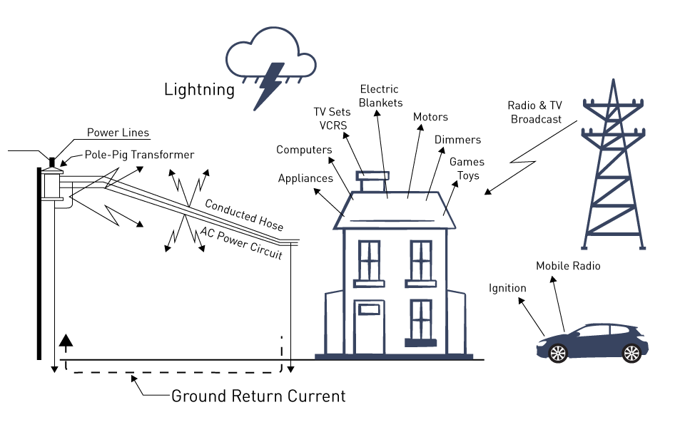
Figure 1: Sources of EMI
Internal Sources of EMI
Switching Noise from Electronic Components: Switching noise from electronic components can be a significant source of electromagnetic interference (EMI). Transistors and diodes, among other components, can generate switching transients that contribute to this issue. Rapid switching times can produce substantial high-frequency noise, especially in power electronic devices.
Clock Signals: The clock circuits in digital systems produce square waves that contain a wide range of harmonics. These harmonics have the potential to emit electromagnetic interference or interfere with other components of the circuit.
Power Supplies: Switch-mode power supplies (SMPS) are notorious for generating electromagnetic interference (EMI) as a result of their high-frequency switching operation. EMI can appear as conducted emissions via power lines or as radiated emissions.
Inductive and Capacitive Coupling: When dealing with a densely packed PCB, it's important to be aware of the potential EMI issues that can arise from inductive and capacitive coupling between adjacent traces and components. This is especially common in high-speed digital circuits, where maintaining signal integrity is of utmost importance.
External Sources of EMI
Electromagnetic Fields from Other Devices: Other devices in the vicinity can emit electromagnetic fields that may disrupt isolated systems. Typical suspects involve motors, transformers, and other high-current devices.
Radio Frequency Interference (RFI): RFI can be a significant issue for systems that rely on signal processing. Sources such as wireless communication devices, radio transmitters, and broadcast antennas have the potential to penetrate isolated systems and cause disruptions.
Electrostatic Discharge (ESD): When someone comes into contact with an electronic device, it can lead to electrostatic discharge (ESD) events. These events have the potential to cause transient electromagnetic interference (EMI), which can result in data corruption or harm to delicate components.
Lightning and Power Surges: External events such as lightning strikes and power surges have the potential to cause transient EMI, which can be extremely detrimental and result in the complete failure of electronic systems.
System Design Considerations
Importance of Identifying EMI Sources: The first step in reducing the impact of electromagnetic interference (EMI) is to identify the precise sources of EMI within and surrounding an isolated system. This knowledge guides the development of designing, filtering, and shielding techniques for efficient EMI management.
Impact on System Performance: Unmanaged EMI can cause a variety of problems, from little performance hiccups to total system failure. The effects of electromagnetic interference (EMI) can be especially serious in sensitive applications like aerospace and medicine.
Techniques for EMI Reduction
Ensuring the proper management of electromagnetic interference (EMI) is crucial to maintaining electromagnetic compatibility (EMC) in isolated systems. This section delves into different design strategies and highlights the significance of grounding and layout optimization in reducing electromagnetic interference (EMI).
Design Strategies for Minimizing Electromagnetic Interference
Use of Differential Signaling: The utilization of differential signaling, which involves transmitting signals as a pair of opposite polarities, proves to be highly effective in minimizing electromagnetic interference (EMI). By employing this technique, the occurrence of common-mode noise is greatly reduced, as the noise tends to be eliminated when the differential signal is received.
Control of Switching Frequencies: Controlling the switching frequencies in circuits with switching elements such as SMPS or digital processors can greatly reduce EMI. One aspect to consider is choosing frequencies that have a lower chance of causing interference with other components of the system, or avoiding frequencies that could create harmonics.
Proper Decoupling and Bypassing: Placing decoupling capacitors near the power supply pins of integrated circuits is crucial for minimizing noise. These capacitors create a direct route for high-frequency noise to be grounded, effectively reducing its impact. By utilizing bypass capacitors, voltage spikes can be effectively filtered out and the power supply can be stabilized. PCB Trace
Routing and Layer Management: Strategically routing PCB traces and utilizing multiple layers can effectively minimize EMI. Implementing strategies to mitigate electromagnetic interference (EMI) involves techniques such as isolating high-speed signals from sensitive areas, employing ground planes to shield traces, and minimizing the length of traces.
Cable and Connector Shielding: Shielding cables and connectors is crucial in preventing the infiltration or escape of EMI in systems that rely on these components. This includes using coaxial cables or shielded twisted-pair cables and ensuring connectors are properly grounded.
Importance of Grounding and Layout Optimization
Effective Grounding Techniques: A properly implemented grounding system plays a crucial role in reducing electromagnetic interference (EMI). One important aspect of this role is to establish effective grounding techniques to minimize noise currents. This includes implementing single-point grounding for low-frequency circuits and multi-point grounding for high-frequency circuits.
Ground Plane Design: Utilizing ground planes on PCBs establishes a reliable reference point for all signals, effectively minimizing the impact of noise. It functions as a protective barrier and decreases the loop area for signal currents, resulting in a decrease in radiated EMI.
Minimizing Loop Areas: Reducing loop areas in PCB layouts and within components is crucial for minimizing EMI. Arranging components and routing traces in a strategic manner helps to minimize the area enclosed by signal and return paths.
Separation of Noisy and Sensitive Components: Ensuring the separation of noisy and sensitive components is crucial to maintaining signal integrity on the PCB. By physically isolating high-speed or high-power components from sensitive analog components, the risk of EMI interference is minimized.
EMI Simulation and Modeling: Using EMI simulation tools during the design phase can help identify and address potential EMI issues, allowing for layout optimizations. These tools have the capability to simulate the propagation of electromagnetic fields within the design and provide suggestions for enhancements.
Filtering and Shielding
Managing and mitigating electromagnetic interference (EMI) is crucial in the context of EMC. Filtering and shielding techniques play a vital role in achieving this. It is crucial to have a well-designed and properly implemented system to effectively suppress noise and control electromagnetic interference in electronic systems.
Designing Effective Filters for Noise Suppression
Fundamentals of Filter Design: Filters are essential for eliminating unwanted noise frequencies and allowing only the desired signals to pass through. It is therefore crucial to have a thorough grasp of the noise spectrum and the operating frequencies of the system.
A few types of filters are listed below:
Low-Pass Filters: Low-pass filters are frequently employed to eliminate high-frequency noise, permitting only frequencies below a specific threshold, referred to as the cut-off frequency, to pass through.
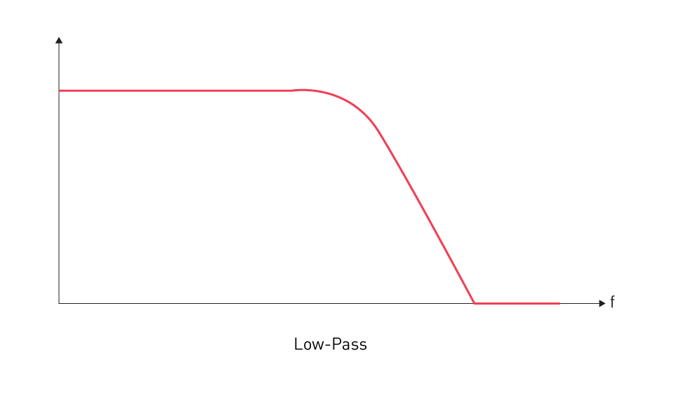
Figure 2: Low-Pass Filter Frequency Response
High-Pass Filters: High-pass filters are used to eliminate low-frequency noise and allow signals above a specific frequency to pass through.
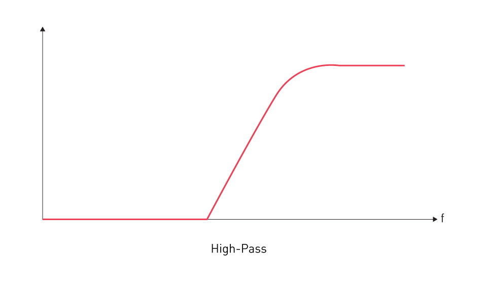
Figure 3: High-Pass Filter Frequency Response
Band-Pass and Band-Stop Filters: Engineered to enable or restrict a particular range of frequencies, respectively.
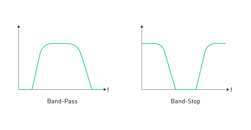
Figure 4: Band-Pass Filter (Left) and Band-Pass Filter (Right) Frequency Response
Component Selection: Selecting the right components for filters, including capacitors, inductors, and resistors, is of utmost importance. It is important to carefully choose these components based on their frequency response, quality factor, and power handling capabilities.
PCB Layout Considerations: When it comes to PCB layout considerations, the placement and routing of filter components on a PCB play a crucial role in determining their effectiveness. Ensuring minimal parasitic inductances and capacitances is crucial, and is achieved by placing components in close proximity to each other and the source of the noise.
Simulation and Testing: By utilizing software tools, one can simulate and test the performance of filters to accurately predict their effectiveness in suppressing noise. Testing the filter design under real operating conditions is essential for validation.
Implementation of Shielding Techniques for EMI Control
Principles of Shielding: The concept of shielding revolves around the creation of a barrier using conductive or magnetic materials. This barrier serves the purpose of preventing electromagnetic fields from either entering or exiting a designated area. Shielding is crucial for safeguarding sensitive circuits from external electromagnetic interference (EMI) and minimizing the emission of EMI from electronic systems.
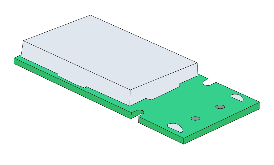
Figure 5: EMI Shielding
Material Selection: When selecting the shielding material, various factors such as the nature of the EMI (electric or magnetic), the frequency range, and any environmental factors are taken into account. Typical materials used are metals such as copper or aluminum due to their excellent conductivity.
Enclosures and Shields: When it comes to achieving optimal EMI control, it is crucial to ensure that enclosures and shields are designed in a way that provides complete coverage to vulnerable areas. It is important to make sure that the shield is properly grounded and that there are no gaps or discontinuities that could weaken its effectiveness.
Cable Shielding: It is important to consider cable shielding as cables have the potential to act as antennas, which can result in the pickup or radiation of EMI. Utilizing shielded cables, which feature a conductive layer enveloping the core conductors, can help alleviate thiProper grounding of the shield is crucial for its effectiveness.
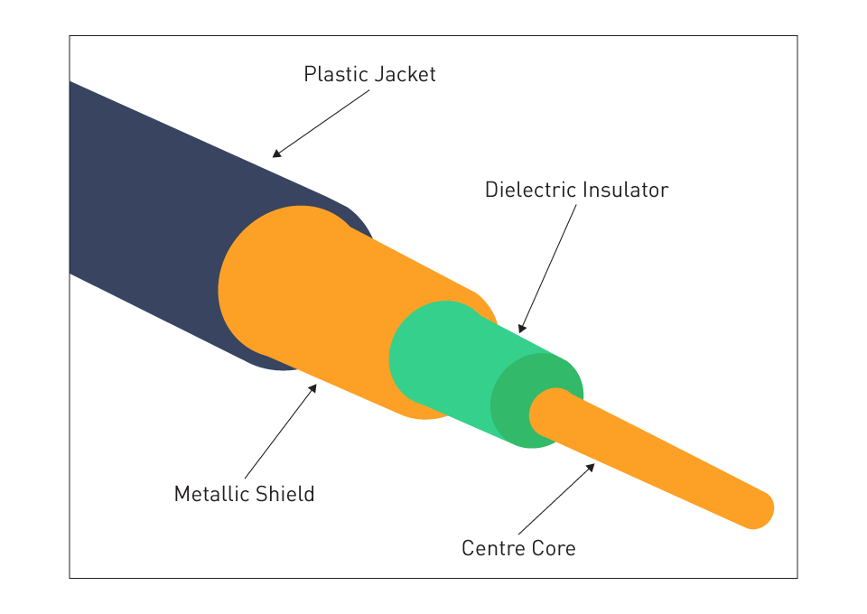
Figure 6: Coaxial Cable with Metallic Shield
Grounding Techniques: Ensuring proper grounding is absolutely essential for achieving optimal shielding. Ensuring a strong connection to the ground is crucial for effectively draining off electromagnetic interference and creating a clear path for it.
Noise Analysis and Simulation
Noise analysis and simulation are crucial to achieving optimal EMC. These processes require the use of different tools and techniques to anticipate, analyze, and confirm the effects of noise on electronic systems, guaranteeing that design decisions are reliable and efficient.
Tools and Techniques for Predicting and Analyzing Noise
Computer-Aided Design (CAD) Software: Electronic systems widely use advanced CAD tools for noise analysis, highlighting their importance in the field. These tools are capable of simulating electromagnetic fields and their interactions with different components, offering valuable insights into potential EMI problems.
Frequency Domain Analysis: This method entails examining the system's response to various frequencies of electromagnetic noise. It assists in detecting resonant frequencies and vulnerable areas within the system.
Time Domain Simulation: Understanding transient behaviors and responses to fast-changing signals is essential to analyzing noise in digital systems.
Network Analysis: Network analyzers are used for measuring parameters such as S-parameters, which provide insights into the behavior of RF signals within a network, encompassing characteristics like reflection and transmission.
EMI/EMC Modeling Software: Specialized software for EMI/EMC modeling enables the simulation of intricate electromagnetic interactions within a system. This includes the ability to analyze radiated and conducted emissions, crosstalk, and shielding effectiveness.
Validating Design Choices through Simulation
Pre-Prototype Analysis: Prior to creating a physical prototype, simulation is used to verify design choices. By identifying and addressing potential EMC issues early in the design process, valuable time and resources can be saved.
Iterative Design Refinement: Through the use of simulation results, designers have the ability to continuously improve and enhance their designs. For instance, when simulation uncovers an abundance of radiated emissions, designers can make changes to PCB layouts, incorporate shielding, or adjust filtering strategies.
Correlation with Physical Testing: Simulations offer a theoretical understanding of noise behavior, but it is essential to validate their accuracy by correlating these results with physical testing. Discrepancies between simulation and actual test results can highlight the need for improvements in models or assumptions.
Custom Simulation Scenarios: Creating custom simulation scenarios that closely resemble real-world operating conditions is possible for specific applications. This focused approach guarantees that simulations are highly relevant and precise.
Design Optimization: In addition to identifying potential issues, simulations can help optimize designs for better performance, cost-effectiveness, and size, all while ensuring EMC compliance. This involves optimizing component placements, selecting materials, and configuring circuits.
Compliance and Testing
Ensuring EMC compliance and effectively managing noise in electronic systems requires thorough testing and strict adherence to standards. This process requires thorough verification of compliance with relevant standards and efficient identification and resolution of EMI issues.
Ensuring EMC Compliance through Testing
Compliance Testing Protocols: In order to ensure that electronic systems meet EMC standards, a set of standardized tests is carried out. These tests usually involve evaluating radiated and conducted emissions, resistance to electromagnetic disturbances, electrostatic discharge (ESD) tolerance, and vulnerability to voltage fluctuations.
Certification from Accredited Bodies: Accredited testing laboratories often perform EMC compliance testing, which requires certification from recognized bodies. Obtaining certification from these organizations is essential to demonstrate your compliance with global and regional EMC standards, such as the IEC, FCC, and EU.
Pre-Compliance Testing: In addition to formal compliance testing, one can conduct pre-compliance testing during the design and development stages. Early-stage testing is crucial for identifying any potential EMC issues before going through the formal certification process.
Regular Compliance Audits: Ensuring compliance is an ongoing process. Regular audits and re-testing are crucial, particularly when there are design changes, component substitutions, or updates to the relevant EMC standards.
Identification and Resolution of EMI Issues
Diagnostic Testing for EMI Issues: When EMI issues are detected, whether during compliance testing or based on feedback from the field, diagnostic tests are performed to precisely identify the nature and source of the problem. Utilizing spectrum analyzers, oscilloscopes, and specialized EMC diagnostic equipment may be necessary.
Root Cause Analysis: Understanding the underlying reasons for the interference is crucial after identifying EMI issues, so a thorough root cause analysis is conducted. This analysis takes into account all aspects of the design, encompassing component selection, circuit layout, and system integration.
Design Modifications: After analyzing the root cause, necessary changes are implemented to address EMI problems. These adjustments may involve modifications to the PCB layout, implementing additional shielding, enhancing filtering, or selecting alternative components.
Iterative Testing and Validation: Once design modifications are made, testing is conducted to ensure that the EMI issues have been resolved. This process guarantees that modifications made to resolve one problem do not unintentionally generate additional complications.
Documentation and Compliance Record Keeping: Thorough documentation of all testing, analysis, and design modifications is essential for record-keeping and compliance purposes. This documentation is crucial for ensuring compliance and serves as a valuable resource for future design projects.



直接登录
创建新帐号