Structural Components of Stepper Motors
Detailed Examination of Rotor, Stator, and Other Components
Stepper motors are characterized by their fundamental components, which include the rotor, the stator, and auxiliary features that permit precise control and movement. These components are responsible for defining structural integrity and its performance. In order to have a proper understanding of how stepper motors operate and how they are intended for particular applications, it is vital to have a firm grasp on these components.
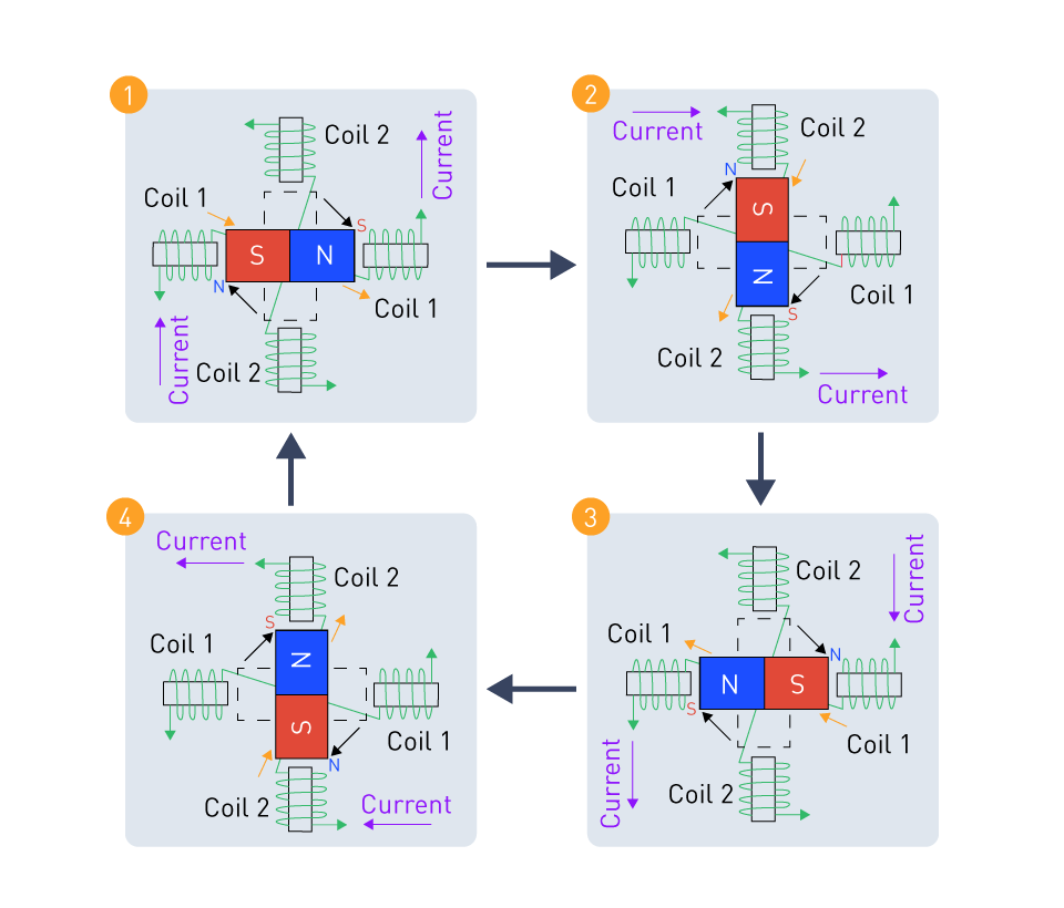
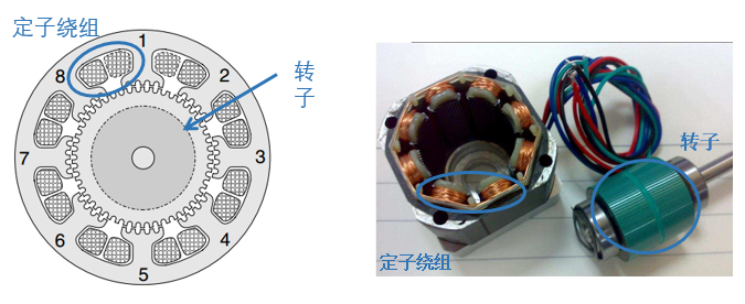
Rotor: The rotor is the moving part of a stepper motor, and the design of the rotor changes depending on the type of stepper motor being used. Permanent magnet (PM) stepper motors are characterized by the construction of the rotor with permanent magnets, which results in the generation of a magnetic field.
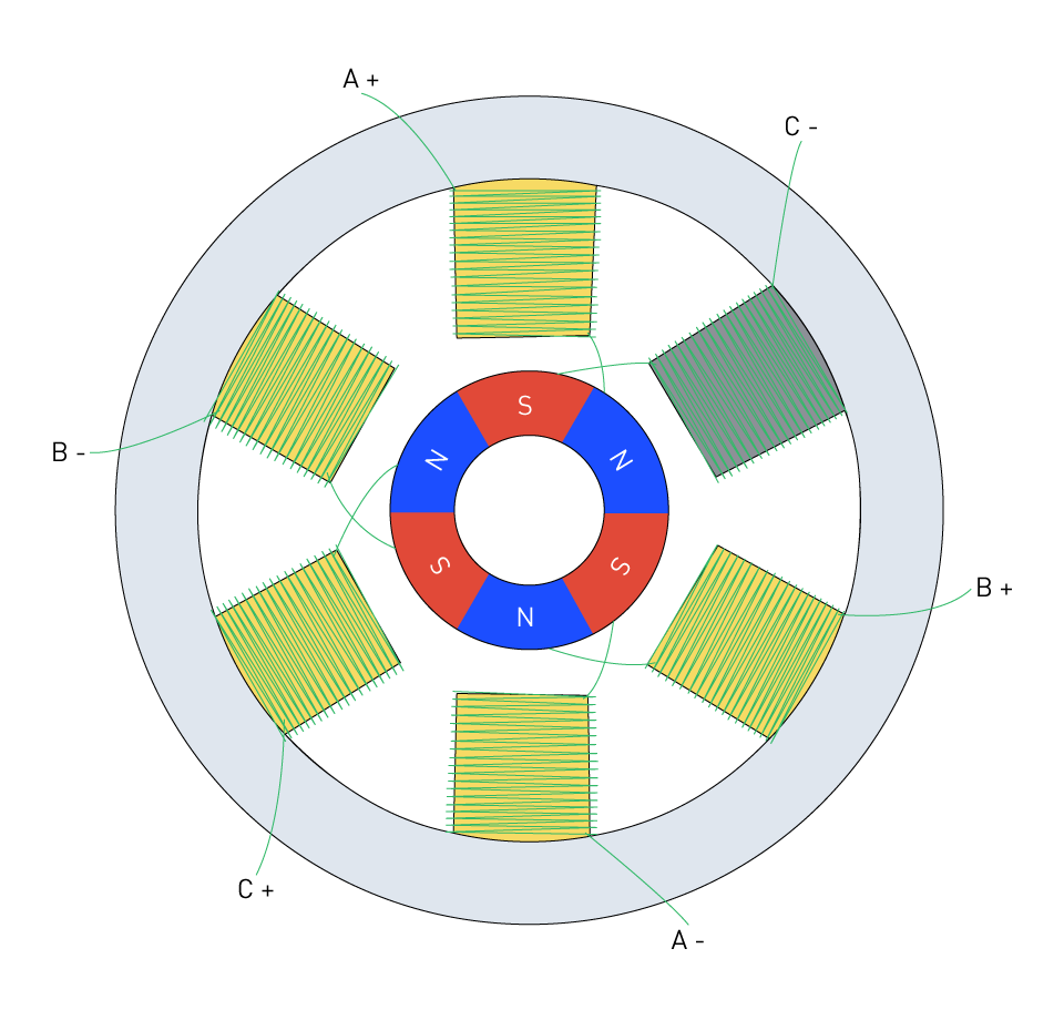
Figure 1: Permanent Magnet Stepper Motor Construction
The rotor of a variable-reluctance (VR) motor is constructed out of soft iron and features teeth that protrude from it. This rotor is meant to align with the magnetic poles of the stator while the motor is operating.
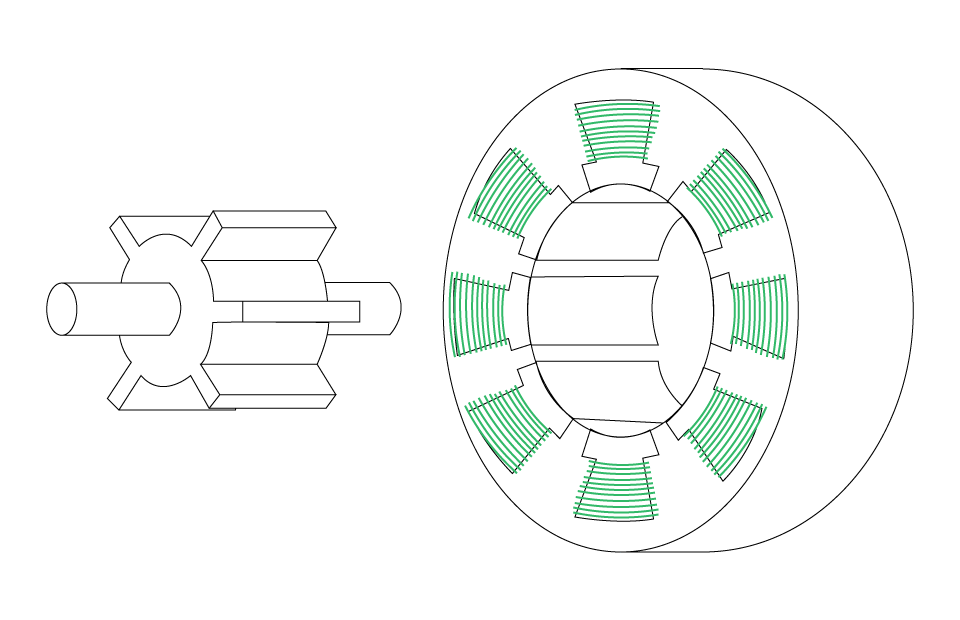
Figure 2: Variable Reluctance Stepper Motor Construction
Stepper motors that are hybrids combine characteristics of both PM and VR kinds. These motors have two-toothed rotors that are embedded with permanent magnets, which allows for increased efficiency and precision.
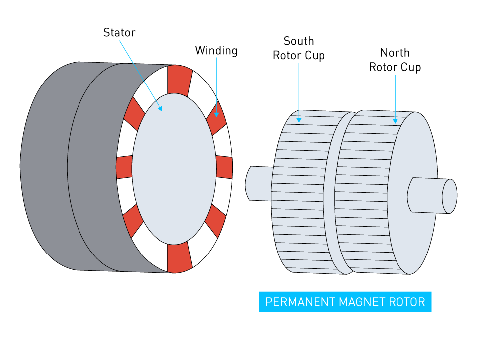
Figure 3: Hybrid Stepper Motor Construction
Stator: The stator is the part of the stepper motor that is stationary and is made up of coils that are twisted around magnetic poles. Through the configuration of these coils and the sequence in which they are energized, a spinning magnetic field is produced, which is what drives the rotor. The design of the stator, which includes the number of poles and coils, has a direct impact on the stepping angle and torque capabilities of the motor.
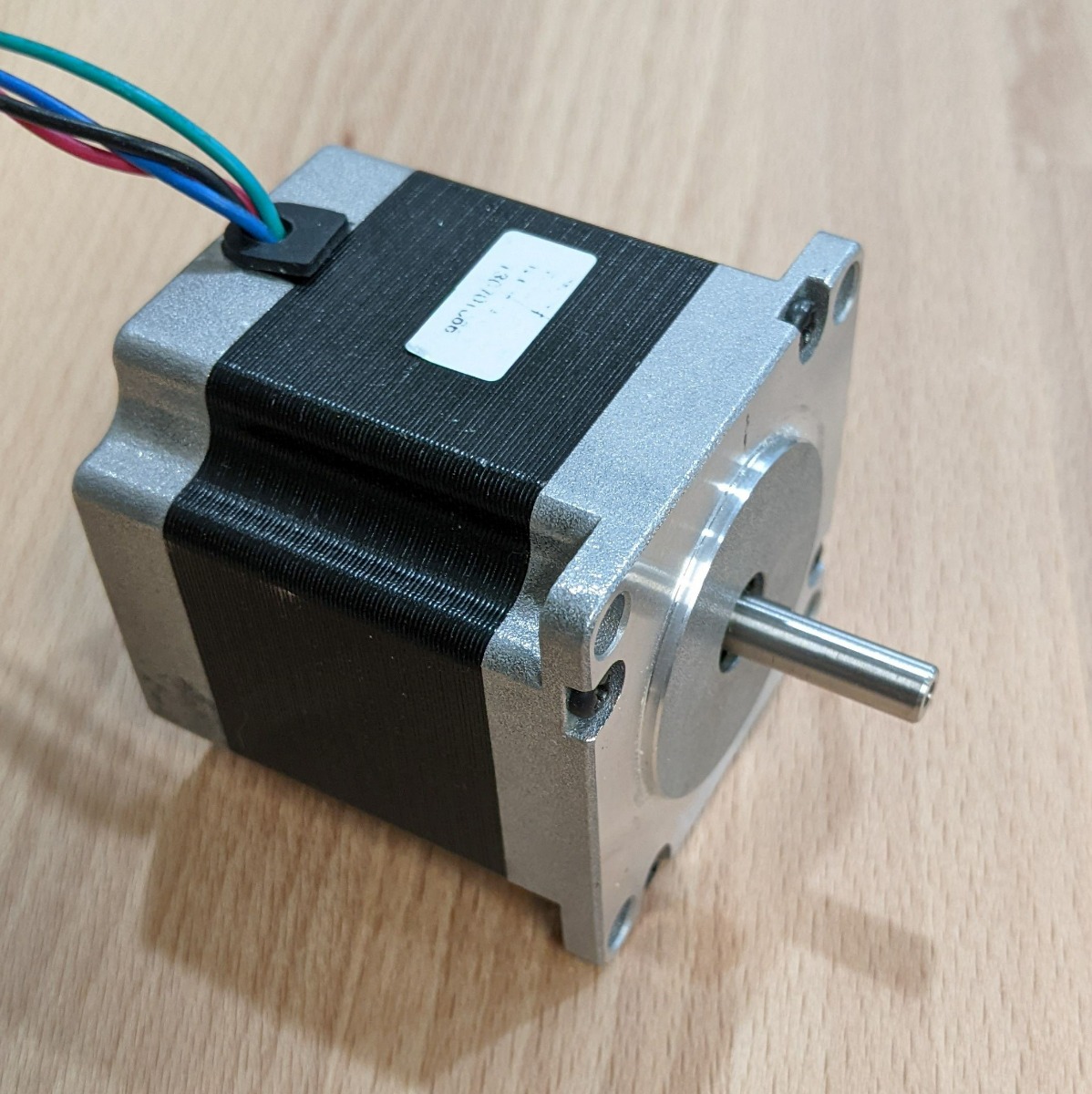
Other Components: Stepper motors consist of a number of other components in addition to the rotor and the stator. These components include bearings that support the rotation of the rotor, a shaft that transmits the motion of the rotor to the application, and a housing that encases the electrical motor. It is possible that the assembly will also have electrical connections, and in certain configurations, gear trains or couplings may also be included.
Material Choices and Construction Impact
There is a considerable relationship between the materials that are utilized in the construction of stepper motors and their performance, durability, and application compatibility.
Magnetic Materials: It is of the utmost importance to select magnetic materials for both the rotor and the stator cores. In high-performance stepper motors, it is customary to use high-grade steel laminations or rare-earth magnets. These materials offer superior magnetic qualities that promote efficiency and stepping precision. These properties include high magnetic permeability, reduced core losses, high resistivity, and strong thermal stability.
Coil Windings: The electrical characteristics of the motor are influenced by the wire that is used for the coil windings of the stator components. Copper is often utilized because of its exceptional conductivity, which allows for an increase in electromagnetic efficiency while simultaneously reducing the amount of heat generated.
Structural Materials: The housing and structural components of stepper motors are typically constructed from metals such as aluminum or stainless steel. These materials offer mechanical strength and heat dissipation capabilities through their construction. The selection of bearing material, such as ceramic or steel, has an effect not only on the motor's longevity but also on the amount of noise it produces while it is in operation.
Impact of Construction: The integration of these materials and components throughout the construction process needs to be precisely handled in order to guarantee the best possible performance from the motor. For example, optimizing the alignment of the rotor and stator can significantly reduce mechanical losses. Additionally, the utilization of high-quality bearings and lubricants can reduce the amount of friction and wear, hence increasing the lifespan of the motor. Additionally, the overall construction has an effect on the motor's resilience to environmental elements such as changes in temperature and vibration, both of which are essential considerations in applications that take place in harsh environments, such as industrial and outdoor settings.
Bipolar and Unipolar Stator Configurations
Stator configurations have a considerable impact on the performance and versatility of stepper motors, notably through bipolar and unipolar arrangements. This is especially true for stepper motors. These configurations govern the manner in which the windings are energized and, as a result, the manner in which the magnetic fields that are used to drive the rotor are generated. For the purpose of selecting the optimal driver and control approach for a particular application, it is essential to have a solid understanding of these setups.
Bipolar Stator Configuration
Every phase of the stator in a bipolar stepper motor includes two windings, and current can flow in either direction through those windings thanks to the bipolar design. Because of this configuration, a more complicated driving mechanism is required. This mechanism must be able to reverse the direction of the current in order to alter the magnetic pole, which will allow the motor to undergo stepping. The reversal of current is accomplished by using an H-bridge circuit for each phase, which enables fine control over the movement of the motor.
Bipolar motors are distinguished by their high torque and performance capacity, which is a direct result of the efficient utilization of all windings in the production of a powerful magnetic field. On the other hand, because of the intricate nature of the driving circuitry, bipolar stepper motors often demand controllers that are more complex and costly.
Unipolar Stator Configuration
Unipolar stepper motors are characterized by their ability to simplify the driving mechanism by enabling current to flow through each winding in only one direction. This is accomplished by dividing each phase winding into two equal halves, with a common center tap for each phase. This allows for the desired result. The motor is operated by sequentially activating these windings, which pulls the rotor into alignment with the magnetic field generated by the winding that has been triggered.
It is not necessary to use H-bridge circuits in order to reverse the flow of current in unipolar motors, which results in control circuits that are less complicated and more cost-effective. The simplicity of this construction, however, comes at the expense of less torque when compared to bipolar configurations. This is because only half of each phase winding is utilized at any given time.
Choosing Between Bipolar and Unipolar
A number of considerations such as the required torque, the complexity of the control, and the limits of cost, are taken into account while deciding between bipolar and unipolar topologies. Due to their higher torque and performance, bipolar motors are well-suited for applications that require precise control and a substantial amount of driving force. Some examples of such applications include CNC machines and robotic components. On the other hand, unipolar motors are frequently utilized in applications where simplicity, cost-effectiveness, and ease of control are of the utmost importance. Applications such as consumer electronics and straightforward automation chores are examples of such applications.
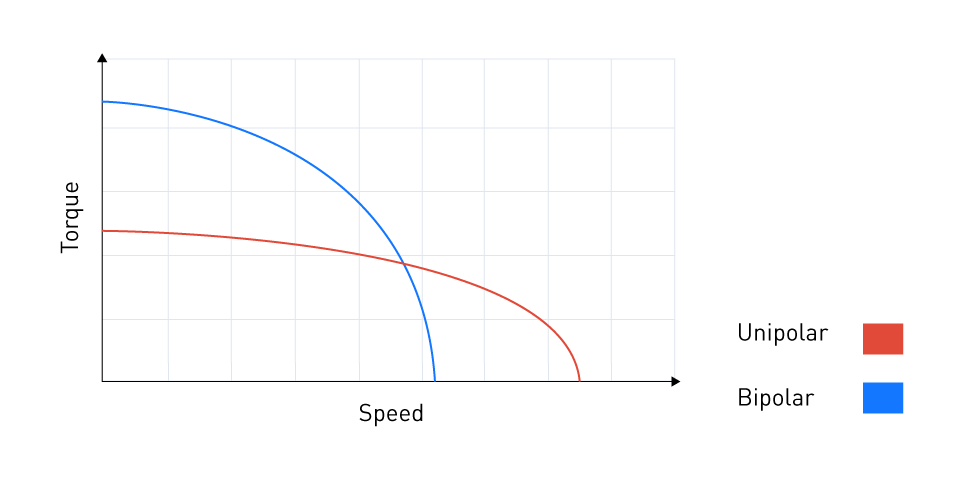
Figure 4: Comparison of typical Speed-Torque Characteristics




直接登录
创建新帐号