Electromagnetic Principles
Fundamental Electromagnetic Concepts Relevant to Motors
Electric motors fundamentally rely on electromagnetic principles for their operation. Describing how electric currents and magnetic fields interact to generate motion, these principles are based on the laws of electromagnetism elucidated by scientists such as Michael Faraday and James Clerk Maxwell. The magnetic field and electromagnetic induction are two key concepts at the core of these principles.
A vector field that envelops magnets and electric currents, a magnetic field represents the force exerted by either a magnet or a current-carrying wire. Consisting of coils of wire through which current flows, electromagnets are typically utilized in electric motors to generate magnetic fields, along with permanent magnets.
The process by which a change in the magnetic field within a coil of wire induces an electromotive force (EMF) in the coil is known as electromagnetic induction. A magnetic field within a coil induces an electric current, constituting the reverse process of the phenomenon described above. A cornerstone of motor operation, Faraday's Law of Electromagnetic Induction quantitatively describes this effect:
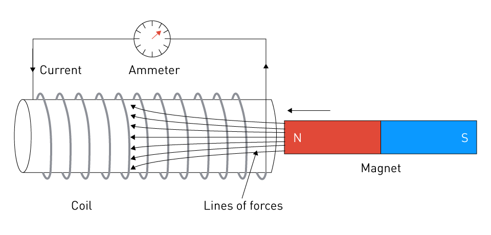
Figure 3: Faraday’s Law of Electromagnetic Induction
The ruling equation is:
$$\varepsilon=-N\frac{d\phi}{dt}$$Where:
ε is the electromotive Force (EMF)
N is the number of turns of the coil
φ is the instaneous change of magnetic flux with time
Magnetic Fields, Torque Generation, and Motor Rotation
The generation of torque and rotation in motors arises from the interaction between magnetic fields and electric currents. In an electric motor, torque is the rotational counterpart of linear force. The magnetic force acting on the current-carrying conductors within the magnetic field gives rise to it.
Consider a scenario where there is a loop of wire with current flowing through it placed within a magnetic field in a simplified context. A force is exerted on the current-carrying wire by the magnetic field. Resulting in the rotation of the loop, this force's direction, according to the Lorentz Force Law, is perpendicular to both the current's direction and the magnetic field. Most electric motors operate based on this fundamental principle of rotation.
Relating the directions of current, magnetic field, and force, the right-hand rule can be employed to ascertain the direction of rotation and the magnitude of torque. The magnitude of torque produced is influenced by factors such as the intensity of the magnetic field, the quantity of current passing through the wire, and the dimensions of the loop.
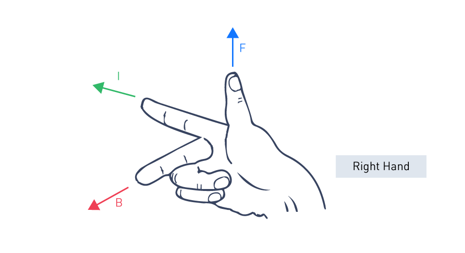
Figure 4: Right-Hand Rule
In practical motors, to sustain continuous rotation, the direction of current in the coils (or the orientation of the magnetic field) must be synchronously switched with the rotation. Accomplished through the utilization of a commutator and brushes or electronic controllers, this process, known as commutation, is vital in DC motors. In AC motors, due to the alternating nature of the current, this effect is naturally achieved.
Basic Motor Mechanics
How Electric Motors Convert Electrical Energy into Mechanical Energy
An electric motor's primary function is the transformation of electrical energy into mechanical energy. Within the motor, magnetic fields and electric currents interact to achieve this conversion. A motor, in its basic configuration, comprises a rotor (the part in motion) and a stator (the part at rest), with either the rotor or the stator creating a magnetic field. Motion is generated by the force created through the interaction between the magnetic field and the electric current coursing through the windings.
Lorentz's force law, which dictates that a conductor carrying current within a magnetic field encounters a force perpendicular to both the current's direction and the magnetic field, underpins this transformation principle:
$$F=q\left(E+v\times B\right)$$Where:
F is the force experienced by the charged particle.
q is the charge of the particle.
E is the electric field vector.
v is the velocity vector of the charged particle.
B is the magnetic field vector.
The flow of electric current through the windings on the rotor (or the stator) in a motor generates a magnetic field that interacts with the stator's (or the rotor's) magnetic field. This force generated by the interaction pushes against the rotor, inducing it to rotate.
Basic Operating Principles of Different Motor Types
Although the approach to this conversion varies, different motor types achieve the transformation of electrical energy into mechanical energy through a consistent fundamental principle.
DC Motors: Supplied to the motor either from an external power source or batteries, direct current (DC) motors produce the electric current and magnetic field through direct current. Rotation is attained through the interaction between the magnetic fields generated by the current in the rotor windings and the field produced on the stator. To sustain continuous rotation, the commutator and brushes switch the direction of current in the rotor windings.
AC Motors: AC motors function using alternating current (AC), which undergoes periodic changes in direction. Induction motors and synchronous motors are among the most prevalent types. A rotating magnetic field is generated in the stator of induction motors, inducing a current and subsequently a magnetic field in the rotor, resulting in its rotation. On the contrary, synchronous motors run at a speed directly linked to the current's frequency and necessitate synchronization during startup.
Stepper Motors: With each electrical pulse, stepper motors move in discrete steps, rotating a fixed angular distance. Allowing for precise control over the motor's position, the rotor rotates in step, corresponding to a sequence of pulses.
Servo Motors: Servo motors encompass a control circuit, a feedback device, and the motor as part of a closed-loop system. Capable of precise control over position, velocity, and acceleration, they provide comprehensive management. The control circuit receives information regarding the motor's position from the feedback device, typically an encoder or resolver, and adjusts the motor's operation to align with the input command.
Control and Regulation of Motors
Introduction to Motor Control Systems
Electric motors rely on motor control systems for precise management of their operation, encompassing aspects such as speed, torque, and position. For precise motion regulation, the complexity of these systems can vary significantly, from basic on/off control to advanced closed-loop control systems.
Controllers, at the heart of motor control systems, are electronic devices or sets of devices responsible for governing the motor's performance. In small DC motors, controllers can be simple, such as a rheostat for basic speed control, or complex, like programmable logic controllers (PLCs) and microcontrollers, which are utilized in industrial applications.
Starting and stopping the motor, selecting and regulating speed, controlling or limiting torque, and safeguarding against overloads and faults are among the key functions of a motor control system. Reversing motor direction, sequencing, and synchronized automation with other system components are also facilitated by advanced control systems.
Basic Control Strategies and Feedback Mechanisms
The motor control tactics differ depending on the motor type and the needs of the application. Open-loop control and closed-loop control represent the two main strategies employed in motor control.
Open-Loop Control: In open-loop systems, the controller dispatches a directive to the motor without receiving feedback to confirm the result. This implies that the motor functions according to the input command, irrespective of the actual output. This approach is less intricate and more economical, yet it sacrifices precision since it does not accommodate disturbances or fluctuations in the motor's performance over time.
Closed-Loop Control: Conversely, closed-loop control systems integrate feedback mechanisms. These systems continually adjust the input control signals based on monitoring the motor's output. Typically, sensors like encoders, tachometers, or resolvers provide feedback by measuring parameters such as speed, position, and torque. To minimize any deviation, the controller compares the actual output with the desired output and adjusts the control signals accordingly. Closed-loop systems, thanks to this feedback loop, enable precise motor control, rendering them suitable for applications demanding high accuracy and reliability.
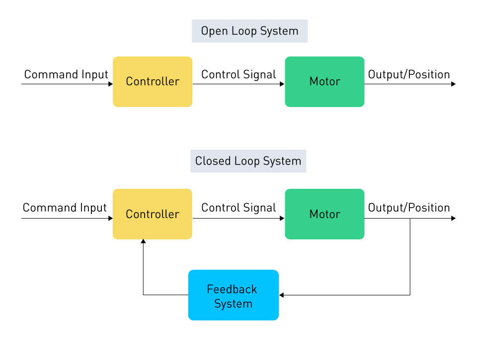
Figure 5: Open-Loop and Closed-Loop Control of Motors
Several control strategies can be utilized within these systems:
Speed Control: Employing pulse-width modulation (PWM) in DC motors or adjusting the supply voltage or frequency (applicable to AC motors) are different methods used to control the motor speed.
Torque Control: In applications like robotic arms or elevators, where the motor must exert a precise amount of force, torque control becomes essential. Controlling the current in the motor windings facilitates this achievement.
Position Control: Position control, prevalent in CNC machines and robotics, entails maneuvering the motor to a particular angle or position. Usually accomplished through closed-loop systems, stepper or servo motors are commonly employed for this purpose.
Sophisticated motor control systems may also integrate advanced methods such as vector control and direct torque control for AC motors, offering enhanced regulation of motor speed and torque. Applications in modern industrial automation, robotics, and precision machinery heavily rely on these systems.




直接登录
创建新帐号