Introduction to Electromagnetic Compatibility (EMC)
In today's automobiles, many electronic systems work in harmony, improving user experience, functionality, and safety. In the vast group of electronic systems, there's always the potential for certain components to emit noises or interferences, thereby disrupting the operations of others. The principles of Electromagnetic Compatibility (EMC) intervene at this phase to establish harmony.
Definition and Importance
Definition: The capability of electrical and electronic systems, equipment, and devices to operate adequately within their electromagnetic surroundings is called Electromagnetic Compatibility (EMC). This involves avoiding introducing intolerable electromagnetic disturbances into the environment or preventing vulnerability to electromagnetic disturbances originating from the environment.
Importance: For safety (like ABS airbags), entertainment, guidance (GPS, sensors for autonomous vehicles), control (ECUS), today’s vehicles rely heavily on electronic systems. In case of failure of any of these systems due to electromagnetic interference, it could compromise both functionality and safety.
Sources of Electromagnetic Interference (EMI) in Vehicles
There are many potential EMI sources due to rising integration of electronic devices in vehicles. Typically spanning many meters within the vehicle, the battery harness supplies power to the electronic consumers. Due to its inherent self-inductance, the harness can experience conducted transients when high-current loads, like the Engine Ignition System, Lighting, or Audio Amplifier, draw power from it or cease consumption. These transients, in turn, affect every other electronic device connected to the harness, necessitating their ability to withstand such disturbances.
Switching mode power supplies and high frequency microcontrollers or communication protocols with adequately large current demand are incorporated in most electronic devices. Within the vehicle, the cable harness serves as a victim antenna, intercepting switching noise from various sources and dispersing it to neighboring electronic devices through diverse coupling mechanisms.
Devices for wireless communication, such as Wi-Fi, Bluetooth, and cellular modules, have the potential to emit noise directly into their surroundings. Hence, their permissible power levels must be constrained.
Magnetic and Electric Noise Sources
The functioning of sensitive electronic components can be interrupted by both electric and magnetic noise sources. Their effective management necessitates a thorough understanding of their nature and sources.
Nature of Noise Sources with Practical Examples
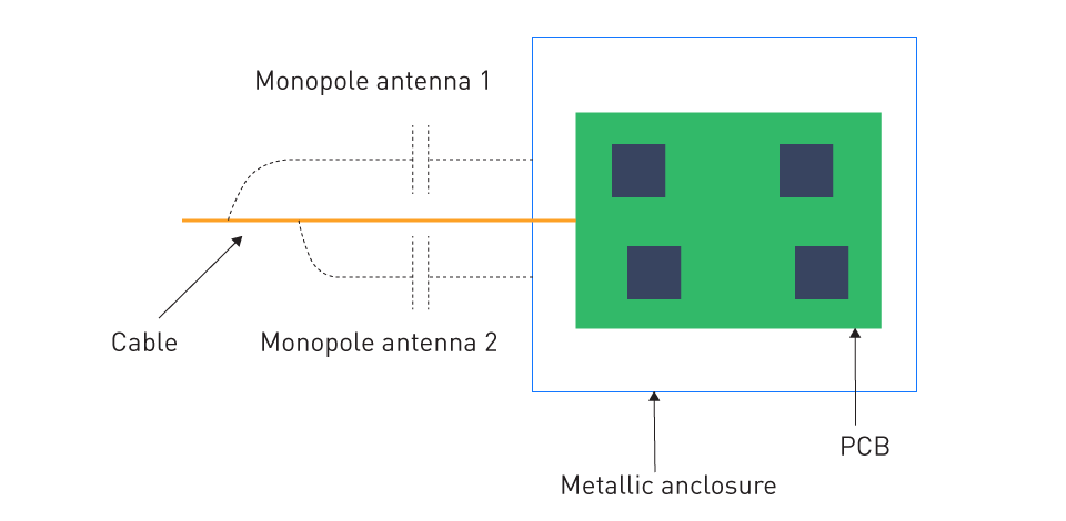
- Electric Noise Sources: Electric fields originated from voltage differences, are typically associated with electric noise sources. For instance, take the cable harnesses of electronic devices, which are known for their tendency to create either monopole or dipole antennas when interacting with the device enclosure or PCB ground plane. Operating on the voltage disparities induced by minor yet rapid leakage currents, these antennas utilize the differences between the cable conductor and the conductive surface of the enclosure/PCB.

Figure 1: Cable Monopole Antenna
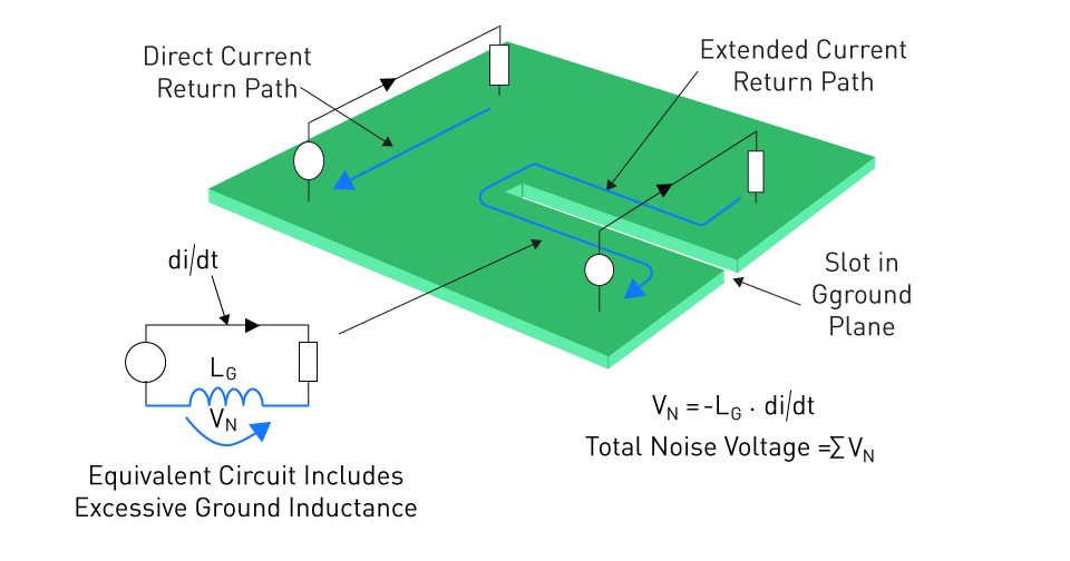
- Magnetic Noise Sources: When an accidental loop antenna is formed in the circuit, this type of noise is generated. Magnetic fields are produced perpendicular to the loop’s plane when current flows through the circuit of the loop antenna. The formation of ground loops, where the return current of the consumer needs to take a long path, is a common problem with circuit designs.

Figure 2: Long Ground Return Loop on the PCB
Coupling Methods
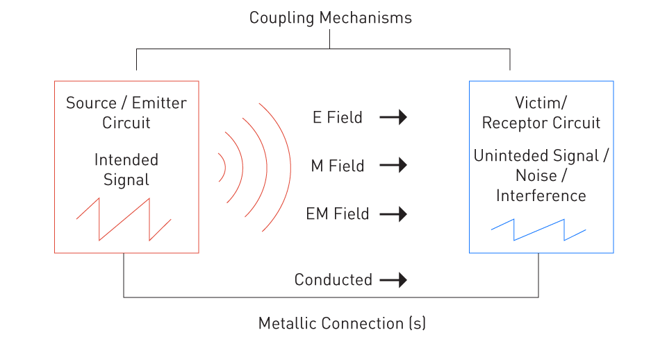
- Capacitive Coupling (E Field): The phenomenon arises when a shifting electric field induces a voltage alteration across two conductors. For example, due to capacitive coupling, a wire conveying a high-frequency signal could cause a voltage to be induced in a nearby wire, possibly resulting in interference.
- Magnetic (M Field) Coupling: Here, a shifting magnetic field within one conductor prompts the generation of a current within a neighboring conductor. Within vehicles, a notable illustration is the alternator, renowned for producing noise that infiltrates audio systems, resulting in the recognizable "whine" emitted from speakers in sync with engine RPM.
- Radiated (EM Field): If the noise source’s frequency is large enough to consider the victim, electronics in the “far-field” range, a coupling becomes radiated type. In the "near-field," noise manifests as either capacitive or magnetic in nature. However, as one moves farther away from the source, the emission undergoes a transition, evolving into independent electromagnetic waves that travel through the air as radiation.
- Conducted: When the noise source has a direct galvanic connection with the victim circuit, conducted coupling occurs. When high current loads are producing voltage fluctuations in the battery supply to other loads, we can see this type of coupling on the battery harness.

Figure 3: Types of Noise-Coupling Mechanism
Understanding and managing EMC becomes imperative as vehicles embrace more advanced electronics and systems. Effective strategies can be devised to minimize the potential effects by identifying the origins of interference and understanding their characteristics. This ultimately results in vehicle safety, reliability, and overall enjoyment for users.
Differential Mode and Common Mode Noises
- Differential Mode Noise: When currents travel in opposite directions through a pair of conductors, typically in a closed loop circuit, differential mode noise occurs. Due to the operation of electronic components such as motors or switches in automotive electronics, differential mode noise frequently arises in power supply lines and signal lines. For instance, the scenario where the activation and deactivation of a motor in a vehicle result in the generation of differential mode noise, affecting the performance of adjacent electronic circuits. Differential mode noise is characterized by noise currents of equal magnitude flowing in opposite directions within the loop.
- Common Mode Noise: Whereas noise currents that flow in the same direction on multiple conductors are common mode noise. Typically, from external sources, it is often coupled to the conductors through electromagnetic fields. For example, high-power radio transmitters or the electrical systems of other vehicles can generate electromagnetic fields, leading to the induction of common mode noise in a vehicle's wiring harness. Sensitive electronics, like radio receivers or GPS, can be affected by this type of noise as it flows through the power lines or ground plane, which creates disturbances.
These two types of noises need different suppression tactics, so the distinction between them is imperative. Differential mode noise can frequently be managed by altering circuit designs and implementing shielding. However, addressing common mode noise usually necessitates the deployment of filters like common mode chokes, which effectively dampen noise currents flowing uniformly across all conductors.
Automotive EMC Standards and Regulations
Safety is of utmost importance in the swiftly advancing field of automotive electronics, where guaranteeing the safe operation of vehicles amid a complex network of electromagnetic interactions is essential. Directing manufacturers in the design, testing, and certification of electronic systems, automotive EMC standards and regulations function as benchmarks. This ensures that these systems neither become vulnerable to external electromagnetic disturbances nor generate excessive interference.
International and Regional EMC Standards
To govern EMC practices in the automotive sector, the international community has recognized the need for consistent standards. Numerous standards organizations globally have introduced guidelines:
International Special Committee on Radio Interference (CISPR): Around the globe, many automotive manufacturers have adopted CISPR 25 standard (a de-facto standard). The emphasis lies on establishing boundaries and measurement techniques for radio disturbance attributes applicable to boats, vehicles, and internal combustion engines.
Society of Automotive Engineers (SAE): J1113 and J551, published by SAE, delineate limits and testing methodologies for diverse electromagnetic emissions and susceptibilities relevant to vehicles.
Regional Standards: Specific adaptations or additional requirements to these international standards may vary across different geographical regions. For example, Japan has JASO, Europe has the ECE R10 standards, and the USA uses standards from the Federal Communications Commission (FCC).
Automotive OEM Requirements
Proprietary EMC requirements enforced by Original Equipment Manufacturers (OEMs) often exceed industry standards in stringency. The basis for these requirements lies in the unique operational and design considerations inherent to each manufacturer's vehicle lineup. OEMs can ensure a higher level of performance and dependability across their fleet by controlling these standards.
EMC Frequency Bands
For both testing and mitigation, an understanding of the frequency bands is crucial. Clarity is offered regarding the frequencies requiring monitoring and control for EMI.
What the Emission Frequency Bands Represent
Frequency bands of emissions delineate segments of the electromagnetic spectrum where electronic devices may emit radiation, whether deliberate (e.g., radio transmitters) or unintentional (e.g., emissions from a motor driver). In automotive EMC testing, thorough examination of these bands is conducted to verify emissions remain within designated thresholds, thus preventing vehicular electronics from causing interference with other devices such as broadcast radios and mobile phones.
Practical Examples On The Consequence of Violating The Thresholds
- Radio Interference: In the AM radio frequency bands, an improperly protected alternator can emit electromagnetic noise. When tuning to certain AM stations, a driver might experience this as static or interference.
- Safety Systems Malfunction: The emission of interference from a high-power electronic component, like an EV inverter, may disrupt the optimal performance of a nearby safety-critical sensor, posing a potential risk to vehicle safety.
- Communication Disruption: Due to unintended vehicular emissions, devices operating on cellular frequencies might face disruptions. It results in poor connectivity inside or near the vehicle or dropped calls.
In conclusion, adherence to a combination of proprietary, regional, international standards are required when navigating the landscape of automotive EMC. A safer, and more reliable vehicular electronic system is guaranteed by recognizing the importance of frequency bands and understanding the real-world implications of electromagnetic emissions.
Techniques for EMI Suppression
Robust strategies are essential to mitigate Electromagnetic Interference (EMI) in response to the increasing complexity of modern vehicles, characterized by many electronic systems. Employing various EMI suppression techniques is crucial to guaranteeing reliable operation and preventing detrimental interference with both internal and external electronic systems of the vehicle.
Shielding and Grounding
Shielding: Averting the escape of unwanted electromagnetic emissions, this is the technique of enclosing an electronic component or system within a conductive barrier. Aluminum, copper, or other specialized conductive polymers are used as common materials for shields. To mitigate interference with or from other vehicle systems, shields are frequently integrated into components such as ECUs, infotainment systems, and sensor interfaces present in automotive applications.
Grounding: Consistent reference potential throughout the vehicle's electronic systems is maintained through proper grounding practices. Additionally, proper grounding facilitates the dissipation of unwanted electromagnetic noise, preventing its coupling into sensitive circuits. Precautionary measures are implemented to prevent the formation of "ground loops," as they have the potential to evolve into unintended antennas or conduits for electrical currents, thereby amplifying interference.
EMI Filters
Circuit components known as EMI filters are crafted to dampen unwanted frequencies, all the while enabling the smooth passage of desired signals. Placed at both the inputs and outputs of electronic modules, they serve to block the entry or exit of EMI within the system. Its examples are:
Capacitors: Capacitors filter high-frequency noise by offering a low impedance return path for the noise and they are connected in parallel with power lines.
Inductors: Inductors offer high impedance to high-frequency noise, thereby acting as a barrier to EMI and are commonly used in series with signal or power lines.
Cable Management and Routing
Effective management and routing of cables are crucial factors in reducing EMI:
Twisted Pairs: Twisting two conductors together minimizes the loop area between them, decreasing susceptibility to differential mode magnetic interference. Such an arrangement effectively neutralizes differential mode noise emission, as the electric current flows in opposite directions within both conductors, thereby counteracting the magnetic fields they generate.
Shielded Cables: A conductive shield around the inner conductor(s) is incorporated by these cables which prevent EMI from coupling into or out of the cable. Depending on whether we want to avert magnetic or capacitive coupling of noise with the environment, the shied needs to be grounded at one end or both ends of the cable. To shield against magnetic noise, grounding the shield at both ends of the cable establishes a return path for the noise current. This generates an external magnetic field that opposes the inner conductor, mirroring the behavior of a twisted pair.
Routing Practices: Attention is paid to distancing cables conveying sensitive signals within the vehicle from potential sources of noise, such as RF transmitters or high-current power cables. Additionally, to minimize the cable's length, proper routing is used, which decreases its susceptibility to interference.
ESD Protection
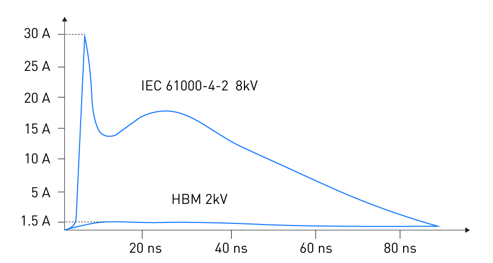
A rapid transfer of electrostatic charge between two objects that occurs in nanoseconds is known as an Electrostatic Discharge (ESD). When an object or person carrying an electrostatic charge contacts the victim circuit, ESD occurs. The flow of ESD current commences as it seeks to equalize charges between the source and the victim circuit. The induction of high currents and voltages reaching thousands of volts by ESD can result in the damage of electronic components or the generation of EMI.

Figure 4: Characteristic Discharge Curves of HBM and IEC 61000-4-2 ESD Waveforms
Protection techniques include:
Protection Diodes: These diodes, commonly integrated into ICs, activate in response to applied ESD overvoltage, offering a pathway for ESD currents to be shunted away from sensitive circuits.
Grounding Straps: These straps, employed during manufacturing and maintenance tasks, serve to align technicians with the electrical potential of the equipment they handle, thus averting the accumulation of electrostatic discharge.
ESD Matting: ESD Matting acts in a similar way to the Grounding Strap. In manufacturing facilities, it is used on workbenches and floors to offer a path for electrostatic charge to dissipate towards Earth.
In automotive electronics, managing EMI is a multifaceted endeavor that demands an amalgamation of component choices, assembly techniques, and design practices. Manufacturers can ensure their vehicles provide dependable, and interference-free operation across their electronic systems by judiciously using the aforementioned methods.
EMC Design Considerations
In automotive electronics, electromagnetic compatibility (EMC) does not only depend on the application of external EMI suppression techniques. At the core of EMC assurance, one finds the foundational elements rooted in the early stages of design. Manufacturers can hugely decrease the susceptibility and emissions of electromagnetic interference by taking a proactive approach to the design of electronic systems. Crucial EMC considerations during the design process are discussed below:
Printed Circuit Board (PCB) Layout
In deciding the electromagnetic behavior of an electronic module, the design of a PCB plays an indispensable role. Major considerations are:
Ground Planes: Loop areas are reduced by integrating a continuous ground plane, thereby reducing inductance and acting as a protection against radiated interference. The disruption of this plane can result in unintended EMI emissions and susceptibility, as illustrated by the example of the loop antenna.
Trace Routing: Careful routing is essential for signal traces. To prevent crosstalk, it's advisable to avoid parallel routing of high-speed digital traces alongside analog or low-level signals. If a trace has a width of "x," it's recommended to maintain at least three times "x" between the center points of two parallel traces of similar width. Adjacent layers carrying high-speed signals should have crossings arranged in perpendicular directions.
Separation of Digital, Power, and Analog Grounds: Digital or high-power noise from coupling into sensitive analog circuits can be prevented by keeping these grounds distinct and connecting them at a single common point.
Component Selection and Placement
The amplification or mitigation of potential EMC issues can be influenced by the selection and placement of components on the PCB.
Decoupling Capacitors: To reduce loop inductance, decoupling capacitors should be placed as close as possible to IC power pins. They ensure stable operation by filtering out high-frequency noise from the power lines.
High-Frequency Components: To avert radiation emissions, components such as oscillators, which work at high frequencies, should be placed away from the board edges.
Connectors: Given that I/O connectors serve as interfaces to the external environment, it is imperative to equip them with sufficient filtering components such as ferrite beads and capacitors. This measure ensures that external noise remains isolated from the system and vice versa.
Grounding Techniques: For EMC, potent grounding is critical and ground loops (a noise source) can be created by numerous ground points. Thus, this risk is reduced by using a single-point ground or ground plane. Moreover, to minimize their impedance, ground traces should be as wide as possible.
Layout of Signal Traces: To prevent cross-talk and noise coupling, high-speed signal traces should be routed away from sensitive analog areas. Moreover, it is advisable to maintain signal traces carrying high currents as short and wide to mitigate resistance and inductance, thereby decreasing electromagnetic emissions.
Shielding Sensitive Components: Sensitive components, like precision analog circuits, must be shielded from electromagnetic interference. Achieving this involves enclosing these components with grounded metal shields or positioning them beneath a grounded copper area on the PCB.
Signal Integrity and Power Integrity
To ensure the EMC of an electronic system both signal integrity (SI) and power integrity (PI) serve a critical role.
Signal Integrity: The quality of a signal, ensuring it remains distortion-free while traveling is referred to as signal integrity. To maintain signal integrity, matched impedance, proper termination, and reducing reflections are mandatory. To reduce the likelihood of undesirable radiated and conducted emissions caused by distorted signals, good signal integrity (SI) is paramount.
Power Integrity: The key consideration for the proper operation of electronic circuits is to maintain a stable power supply that is free from high-frequency noise. Ensuring power integrity (PI) relies heavily on decoupling networks, voltage regulators featuring robust transient response, and meticulously designed power plane configurations.
Automotive electronics designers can ensure their products function reliably in the real world by placing a focus on these EMC design considerations from the outset. Implementing this proactive approach can also diminish the necessity for subsequent modifications or the incorporation of additional EMI suppression techniques, leading to time and cost savings in the long run.


直接登录
创建新帐号