Introduction to Simulation Software in Power Electronics Design
Simulation software is essential for designing and developing power electronics systems. It enables engineers to model, analyze, and optimize circuits and systems before proceeding to physical prototypes, saving time, and money, and lowering design risks. Engineers can test control algorithms, explore how power electronic circuits behave under different operating conditions, and evaluate how component variations and parasitic effects affect system performance by utilizing simulation tools. This section introduces the function of simulation software in power electronics design, emphasizing its significance in modern engineering practices.
The Role of Simulation in Power Electronics Design
Design Validation and Optimization: With simulation software, engineers can correctly model the electrical, thermal, and magnetic properties of power electronic components and systems, allowing them to validate their designs. To find the best configuration that satisfies performance, efficiency, and cost requirements, designers can use simulation to test various topologies, control strategies, and component selections.
Circuit Simulation: Engineers can model the behavior of individual components like transistors, diodes, capacitors, and inductors at the circuit level using simulation tools like Simulation Program with Integrated Circuit Emphasis (SPICE). These tools offer insights into how the circuit performs under various loads and conditions by simulating both steady-state and transient responses.
System-Level Simulation: System-level simulation tools, such as MATLAB/Simulink, allow the modeling of entire power electronic systems, including converters, controllers, and loads, in addition to individual circuits. Before implementing control algorithms on hardware, engineers can design and test them in a virtual environment because of these tools, which make it easier to analyze system dynamics, stability, and control performance.
Predicting Real-World Behavior: One of the fundamental benefits of simulation is its ability to anticipate real-world behavior of power electronic systems under a variety of conditions. In addition to the effects of electromagnetic interference (EMI) and power quality issues, engineers can model the effects of temperature fluctuations, voltage variations, and component tolerances. Designing resilient systems that can function reliably in a variety of environments requires this predictive capability.
Iterative Design Process: Simulation enables an iterative design process in which engineers can enhance and optimize their designs across several cycles of modeling, analysis, and adjustments. With the use of this method, an extensive design space can be explored, allowing for the early detection of possible issues and the development of creative solutions that traditional design methods might fail to notice.
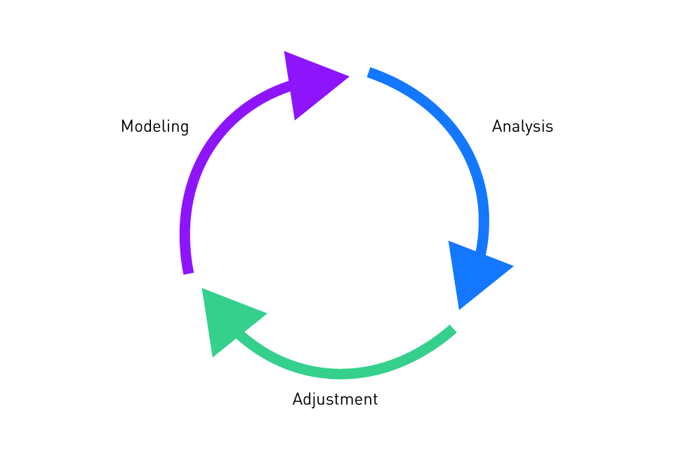
Figure 1: Iterative design
Cost and Time Efficiency: Simulation reduces development costs and speeds up time-to-market for new products by eliminating the need for physical prototypes. Engineers can identify and fix potential design flaws via virtual prototyping before they become expensive issues in the manufacturing stage. Furthermore, simulation tools offer rapid testing of multiple design iterations, allowing for the speedy evaluation and comparison of various design options.
Table 1: Benefits of simulation for power electronics design
| Benefit | Description |
|---|---|
| Reduced Development Time | Engineers can test and validate designs without physical prototypes, speeding up the design process |
| Cost Savings | By detecting potential issues early in the design phase, simulation minimizes the need for costly prototyping and testing |
| Design Optimization | Circuit parameters can be tweaked and optimizedto improve performance |
| Risk Reduction | Simulation helps to identify and address design flaws, preventing expensive failures and reducing the risk of component damage |
| Enhanced Control | Engineers can simulate various operating conditions to better understand system behavior and enhance control strategies |
| Complex System Modeling | Simulation tools can model complex power systems that are difficult or expensive to analyze physically |
| Thermal and Electromagnetic Analysis | Prediction of heat dissipation and electromagnetic interference allows for better thermal and shielding designs |
| Integration with Multidisciplinary Tools | Integration with mechanical, thermal, and control system analysis tools provides a comprehensive view of overall system performance |
Types of Simulation in Power Electronics
Circuit Simulation: In power electronics design, circuit simulators such as SPICE are frequently used to analyze circuit behavior in detail. Complex nonlinear phenomena including conduction losses, thermal effects, and switching transients can be modeled with these methods. Circuit simulation is required to verify the performance of power converters, amplifiers, and other electronic circuits at the component level.
DC, AC, and Transient Analysis: Circuit simulators perform a variety of analyses, including DC operating point analysis, AC small-signal analysis, and transient analysis. Engineers can assess frequency response, identify potential stability issues, and comprehend the steady-state and dynamic behavior of circuits with the use of these analyses.
Table 2: Steady-state vs. transient analysis
| Aspect | Steady-State Analysis | Transient Analysis |
|---|---|---|
| Definition | Analysis of circuit behavior when it has reached a steady-state condition, with stable voltages and currents | Analysis of the circuit response to sudden changes, such as switching events, power-up, or load variations, over time |
| Time Dependency | Focuses on the long-term behavior, where all time-varying components have settled | Examines how the circuit behaves over short periods, capturing how it responds to changes or disturbances |
| Key Focus | Steady operating conditions such as voltage levels, current flow, and power | Initial and dynamic behavior like switching transients, voltage spikes, and current ripple |
| Relevance | Important for understanding the long-term performance of a system under normal conditions | Crucial for understanding the system's response to non-ideal conditions, such as inrush current or voltage spikes |
| Applications | Used for evaluating final performance (e.g., efficiency, voltage regulation) after a system stabilizes | Used to design circuits that handle initial power-on conditions, switching, and load variations effectively |
System-Level Simulation: System-level simulation uses tools such as MATLAB/Simulink, which focuses on the overall behavior of the power electronics system rather than individual components. These tools enable the simulation of complicated interactions across many subsystems, including power converters, control algorithms, and load dynamics.
Control System Design: System-level simulation is very useful for control system design, allowing engineers to develop and evaluate control strategies in a virtual environment. Engineers can improve control parameters, test stability, and evaluate performance under various operating conditions by simulating the full system, which includes the power stage, sensors, and controllers.
Electromagnetic and Thermal Simulation: In addition to electrical simulation, power electronics design frequently requires the examination of electromagnetic and thermal effects. Electromagnetic simulation tools, such as ANSYS Maxwell, are used to simulate magnetic components including inductors and transformers, as well as to evaluate EMI. Thermal modeling technologies, such as COMSOL Multiphysics, assist engineers in predicting temperature distribution and identifying potential hotspots in power electronic systems, assuring stable operation and averting thermal failure.
Co-Simulation: In some cases, combining various simulation techniques is required to fully represent the complexity of a power electronics system. Co-simulation is the simultaneous use of multiple simulation tools, such as electrical and thermal simulation or circuit and system-level simulation. This approach offers insights that would be impossible with a single simulation tool and enables a more thorough examination of the behavior and performance of the system.
The Importance of Simulation in Modern Engineering Practice
Design Verification and Compliance: For verifying that power electronics designs adhere to legal and industrial standards; simulation is a crucial tool. Engineers can guarantee adherence to efficiency, safety, and electromagnetic compatibility (EMC) requirements by modeling the system's behavior under different operating conditions. Additionally, simulation helps in the detection of possible issues that can compromise reliability, enabling engineers to make the required design modifications before moving to production.
Innovation and Experimentation: Simulation software gives engineers a platform to experiment and be creative, allowing them to push the limits of power electronics and explore new design concepts. Engineers can create cutting-edge solutions that improve performance, lower costs, and improve the functionality of power electronic systems by simulating hypothetical scenarios and testing unconventional approaches.
Collaboration and Communication: Simulation tools make it easier for teams such as circuit designers, control engineers, and thermal analysts to collaborate in a multidisciplinary engineering environment. Team members can collaborate more efficiently and guarantee that all design aspects are aligned and that any possible conflicts are resolved early in the development process by sharing simulation models and results.
Continuous Improvement: The initial design phase is not the only time simulation is used. Additionally, simulation tools are employed in post-production for performance enhancement and troubleshooting, as well as in the testing, validation, and optimization stages. Continuous improvement through simulation guarantees that power electronics systems continue to be competitive and reliable throughout their lifecycle.


Comparison of Popular Simulation Tools
Simulation software is crucial for the design, analysis, and optimization of circuits and systems in the field of power electronics. There are numerous tools available, each with special features tailored to specific aspects of power electronics design. Some of the most widely used simulation tools, including SPICE, MATLAB/Simulink, LTspice, and LabVIEW, are compared in this section with a focus on their advantages, applications and disadvantages. Understanding the features and best-use cases of these tools can assist engineers in selecting the optimal software for their specific needs.
Simulation Program with Integrated Circuit Emphasis (SPICE)
Developed at the University of California, Berkeley, SPICE is a standard for simulating analog circuits, including power electronics, and is one of the most popular and established circuit simulation tools in the electronics industry.
Key Features:
Circuit-Level Simulation: SPICE excels at thorough circuit simulation, allowing engineers to model the behavior of individual components including diodes, inductors, and transistors. It offers a high degree of precision for examining circuit performance in different conditions.
Support for Nonlinear Components: SPICE is an optimal tool for simulating switching circuits, such as those in power converters, because it can handle nonlinear components and their dynamic behavior.
DC, AC, and Transient Analysis: Analysis options provided by SPICE include time-domain transient analysis, AC small-signal analysis, and DC operating point analysis. These features are crucial for analyzing power electronic circuits' dynamic and steady state.
Applications:
Power Supply Design: SPICE is widely used to build and optimize power supplies such as linear regulators, buck converters, boost converters.
Analog Circuit Design: For the design and simulation of analog circuits that need exact control and stability, including amplifiers and filters, SPICE is perfect.
Limitations:
Steep Learning Curve: Compared to other modern tools, SPICE has a more challenging learning curve, specifically for beginners. For beginners, the text-based interface and the requirement for detailed component models can be challenging.
Limited System-Level Simulation: SPICE is ideal for circuit-level analysis, but it is less suitable for system-level simulation, which requires consideration of interactions between multiple subsystems.
MATLAB/Simulink
MathWorks developed MATLAB/Simulink, a powerful environment for modeling, simulating, and evaluating dynamic systems such as power electronics. Simulink, an add-on, offers a graphical interface for developing models with block diagrams, making it accessible to users of diverse levels of experience.
Key Features:
System-Level Simulation: Simulink excels in system-level simulation, enabling engineers to simulate complete power electronic systems, including converters, controllers, and loads. It allows the integration of multiple subsystems, making it excellent for complex designs.
Control System Design: MATLAB/Simulink is extensively used to develop and test control algorithms for power electronics. Its large library of control blocks, along with the ability to model feedback loops, make it an excellent tool for control system engineers.
Flexible Modeling Environment: The block diagram approach of Simulink enables simple system parameter adjustment and straightforward modeling. Multi-domain analysis is made possible by its capability for co-simulation with other tools.
Applications:
Power Converter Design: Simulink is widely used for developing and simulating power converters, including inverters, rectifiers, and DC/DC converters. It is very useful for designing and testing control techniques in these systems.
Embedded Systems: The development of embedded systems, including automatic code generation for digital signal processors (DSPs) and microcontrollers, is supported by MATLAB/Simulink.
Limitations:
Computationally Intensive: Simulink models can be computationally demanding, requiring a substantial amount of memory and computing power, especially when they are large and complex.
Cost: MATLAB/Simulink is a commercial tool with a high cost, which may be unaffordable for some users, particularly in academic settings.
LTspice
LTspice, developed by Analog Devices, is a free, and widely used SPICE-based simulator made especially for power electronics. Engineers use it for both simple and sophisticated circuit simulations because of its user-friendly interface and extensive component library.
Key Features:
Ease of Use: Compared to traditional SPICE, LTspice provides an easier-to-use interface with drag-and-drop components and simple schematic capture tools. This makes it accessible to both new and seasoned users.
High Speed: LTspice is designed for speed, allowing for rapid modeling of complex circuits. This is especially helpful when performing parametric sweeps or multiple iterations.
Integrated Component Models: It includes a large library of components. This integration makes it easy to develop circuits that use these components.
Applications:
Switching Power Supplies: LTspice is extensively used to design and simulate switching power supplies, covering both isolated and non-isolated topologies.
Analog Circuit Design: Similar to SPICE, LTspice provides comprehensive analysis and optimization tools, making it a good fit for analog circuit design.
Limitations:
Limited System-Level Simulation: Similar to traditional SPICE, LTspice is mostly used for circuit-level simulation and does not have the system-level modeling features of tools such as MATLAB/Simulink.
Component Library Scope: Although LTspice has a large component library, its primary focus on Analog Devices' devices may restrict its applicability when other manufacturers' components are needed.
LabVIEW
National Instruments developed LabVIEW, a graphical programming environment predominantly utilized for industrial automation, instrument control, and data acquisition. It also offers simulation and control system design, making it an extremely versatile tool in power electronics.
Key Features:
Graphical Programming Interface: Users can easily develop complex applications with LabVIEW's graphical programming language, which eliminates the need for traditional text-based coding.
Real-Time Simulation and Control: Engineers can test and evaluate systems in real-world conditions due to LabVIEW's proficiency in real-time simulation and control applications. It performs particularly well in hardware-in-the-loop (HIL) simulations.
Integration with Hardware: A wide range of hardware, including field-programmable gate arrays (FPGAs), programmable logic controllers (PLCs), and data acquisition systems, can be easily interfaced with LabVIEW. For developing and testing power electronics systems with real hardware components, this makes it ideal.
Applications:
Hardware-in-the-Loop (HIL) Testing: LabVIEW is frequently used in HIL testing, which verifies control algorithms and system performance by integrating virtual models of power electronics systems with physical hardware.
Control System Development: LabVIEW facilitates the design and implementation of control systems, particularly in instrumentation applications and industrial automation.
Limitations:
Complexity: While LabVIEW's graphical programming environment is robust, it can also be hard and time-consuming to understand, particularly for users who are new to graphical programming.
Cost and Licensing: Similar to MATLAB/Simulink, LabVIEW is a commercial tool, and some users may find the licensing fees expensive.
Table 3: Comparison of simulator features
| Feature | SPICE | MATLAB/Simulink | LTspice | LabVIEW |
|---|---|---|---|---|
| Type | Circuit simulation software | Mathematical modeling, simulation, and algorithm development | Circuit simulation software focused on analog circuits | Graphical programming environment for system design and test |
| Primary Focus | Analog and mixed-signal circuit simulation | System modeling, control design, signal processing, etc. | Analog and power electronics circuit simulation | Measurement, data acquisition, control systems, and simulation |
| Usage | Circuit design and analysis, especially analog circuits | System-level modeling, signal processing, and control design | Analog and power electronics circuit simulation | Data acquisition, instrument control, system modeling, HIL testing |
| User Interface | Command-line | Graphical user interface (Simulink) with block diagram modeling | GUI for schematic capture and simulation | Graphical programming interface with virtual instrument (VI)-based design |
| Schematic Capture | External tools like OrCAD, Altium, or KiCad | Built-in block diagram (Simulink) or external tools | Built-in schematic capture | Built-in graphical block diagrams (VIs) |
| Simulation Types | DC, AC, transient, noise, parametric sweeps, Monte Carlo analysis | Time-domain, frequency-domain, control system, signal processing | DC, AC, transient, noise, Monte Carlo, FFT analysis | Real-time, system-level simulation, signal processing, control systems |
| Supported Models | Transistors, resistors, capacitors, inductors, diodes, op-amps, etc. | Custom blocks for various models, including physical systems and controllers | Analog components, passive components, power components, SPICE models | Custom block libraries for sensors, actuators, controllers, and physical systems |
| Simulation Speed | Slower for large and complex circuits | Speed depends on the complexity of the model and solver chosen | Fast for analog circuits | Fast for system-level simulations; real-time simulations possible |
| Learning Curve | Moderate (traditional SPICE requires command-line syntax) | Moderate to high (requires learning Simulink block modeling) | Easy to moderate (GUI-based, but detailed circuit knowledge required) | Moderate (easy to start with simple VI programming, more complex systems take time) |
| Customizability | High (via SPICE commands and netlists) | Very high (MATLAB scripting, custom Simulink blocks) | Moderate (custom models via SPICE code) | Very high (using LabVIEW’s graphical programming and scripting capabilities) |
| Cost | Free (varies by specific SPICE implementation) | Paid (MATLAB licensed; Simulink is an add-on) | Free | Paid (LabVIEW requires a license, with additional costs for toolkits) |
| Popularity in Industry | Widely used for analog and mixed-signal circuit design | Widely used in academia and industry for control, signal processing, and algorithm development | Popular for analog and power electronics simulation | Widely used in industries requiring test, control, and measurement applications |
| Model Libraries | Large library of standard components | Extensive libraries for control systems, signal processing, etc. | Large library of analog and power electronics models | Extensive libraries for measurement, control systems, and hardware interfacing |
| Advanced Features | Extensive device-level simulation, noise analysis, etc. | High-level modeling, control system design, signal processing | Focus on analog circuit fidelity, fast solvers | Advanced hardware integration, system-level simulation, HIL testing |
| Compatibility | Open-source SPICE implementations (e.g., ngspice, PSpice) | Can integrate with hardware, external data, and simulation tools | Can import SPICE models, supports .raw and .txt outputs | Excellent integration with NI hardware, third-party devices |
| Integration with Other Tools | Can integrate with external tools like PCB design software | Strong integration with other MathWorks tools (e.g., Simulink) | Can export data to external tools and analyze results in various formats | Can interface with NI hardware, third-party software, and databases |
| Real-time Simulation | Not designed for real-time simulation but can simulate hardware in the loop (HIL) | Real-time simulation possible with Real-Time Workshop | No native real-time simulation, but can be used in HIL setups | Real-time simulation supported with HIL testing |
| Applications | Circuit design, filter design, amplifier analysis, noise analysis | Control systems, signal processing, communications, robotics | Analog circuit simulation, power electronics, sensor systems | Test automation, industrial control, embedded systems, measurement systems |
Selecting the Right Software for Different Applications
A crucial decision in the design and development of power electronics systems is the selection of simulation software. The correct tool can enhance accuracy, speed up the design process, reduce development time, and improve the final product's overall performance. Selecting the best simulation tool for a specific application can be difficult because many options are available, each with unique advantages and disadvantages. This section offers guidance on how to choose the best simulation software depending on the particular needs of different power electronics applications.
Understanding the Application Requirements
Understanding the specific requirements of the application is essential before selecting a simulation tool. Key considerations include:
System Complexity: The selection of simulation software will be influenced by the complexity of the system being developed, whether it consists of simple circuits, complex multi-stage converters, or entire power systems. Tools with advanced system-level simulation capabilities may be required for complex systems.
Level of Detail Required: While some applications may concentrate on system-level behavior and control strategies, others may require detailed circuit-level simulations with accurate modeling of individual components. The selection of tools such as MATLAB/Simulink for system-level modeling and SPICE for circuit-level analysis will be influenced by the required level of detail.
Real-Time Requirements: Real-time simulation capabilities are essential in applications such as control system development and hardware-in-the-loop (HIL) testing. For these instances, tools that easily interface with hardware, such as LabVIEW, are particularly well-suited.
User Experience and Learning Curve: It's also important to consider the technical team's expertise and the software's learning curve. While some tools, such as MATLAB/Simulink, offer more advanced features but have a higher learning curve, others, like LTspice, are easy to use and accessible to beginners.
Circuit-Level Simulation
Circuit-level simulation tools are the ideal option for applications that require in-depth analysis of individual components and circuits.
SPICE and LTspice: These tools are perfect for applications that need detailed design and optimization of analog circuits, power converters, and other discrete components. They are ideal for studying thermal effects, switching behaviors, conduction losses, in circuits.
Applications:
Power Supply Design: For designing reliable and efficient power supplies, such as linear regulators, boost converters, and buck converters, circuit-level simulation is essential.
Analog Circuit Design: SPICE-based tools,like PSpice,offer the accuracy and detail required for precision analog circuits such as amplifiers and filters.
System-Level Simulation
System-level simulation tools are better suited for analyzing the overall behavior of a power electronics system, including interactions between multiple subsystems.
MATLAB/Simulink: For system-level design, this software is perfect, particularly when the application involves feedback loops, control systems, and dynamic component interactions. For simulating complicated systems like grid-tied inverters, multi-stage converters, and renewable energy systems, MATLAB/Simulink is especially powerful.
Applications:
Control System Design: MATLAB/Simulink is a powerful tool for developing and testing control strategies for power electronics systems, such as digital controllers for motor drives and inverters.
Renewable Energy Systems: MATLAB/Simulink provides the tools required to model and optimize system performance when integrating renewable energy sources, such as solar or wind, with power grids and energy storage.
Real-Time Simulation and Hardware Integration
In applications requiring real-time performance and the integration of simulation with physical hardware, selecting a tool that supports real-time simulation and hardware-in-the-loop (HIL) testing is crucial.
LabVIEW: LabVIEW is especially well-suited for HIL testing, control system development, and real-time simulation. Its seamless integration with a variety of hardware platforms makes it perfect for embedded control, automotive systems, and industrial automation applications.
Applications:
Hardware-in-the-Loop (HIL) Testing: LabVIEW is frequently used in HIL testing environments, allowing control algorithms to be validated in real-world conditions by connecting virtual models to physical hardware.
Industrial Automation: LabVIEW offers powerful tools for developing control systems that interact with sensors, actuators, and other industrial devices for applications involving industrial automation and instrumentation.
Co-Simulation and Multi-Domain Analysis
Tools for co-simulation are useful in complex designs that require the integration of multiple simulation domains, such as electrical, thermal, and electromagnetic simulations.
ANSYS and MATLAB/Simulink Co-Simulation: Co-simulation capabilities enable simultaneous analysis of electrical, thermal, and mechanical aspects of power electronics systems. This is especially useful in applications such as electric vehicle powertrains, where both electrical and thermal management must be optimized simultaneously.
Applications:
Electric Vehicle Systems: Co-simulation tools give a thorough understanding of system performance by allowing the examination of the entire powertrain, including motor control, battery management, and thermal management.
Thermal Management in Power Electronics: Co-simulation helps aid in the optimization of heat dissipation and component placement for applications that demand accurate thermal management, such as high-power converters.
Cost and Licensing Considerations
The cost and licensing model of the software are also key considerations, especially for academic institutions, startups, and small companies.
Free and Open-Source Tools: Tools like LTspice are an attractive option for projects with low budgets because they provide strong simulation capabilities at no cost. However, these tools may be limited in terms of system-level modeling and real-time simulation.
Commercial Tools: Commercial tools, such as LabVIEW and MATLAB/Simulink, are more expensive but provide more capabilities and comprehensive support. These tools are often justified in professional environments where the benefits outweigh the costs.
Applications:
Academic and Research Projects: While MATLAB/Simulink is frequently utilized in research institutions that demand more sophisticated capabilities, free tools such LTspice are often sufficient for educational purposes.
Commercial Product Development: Investing in comprehensive tools such as LabVIEW or MATLAB/Simulink can improve the design process and result in better product performance for commercial product development.
Integrating Simulation Software into the Design Process
Integrating simulation software into the power electronics design process is essential for designing high-quality, efficient, and reliable designs. Simulation tools allow engineers to continuously evaluate and enhance their designs throughout the development process, in addition to validating concepts and optimizing performance early in the design cycle. When these tools are properly incorporated into the design process, potential issues are identified and resolved early on, before they become expensive issues later. The best practices and strategies for successfully integrating simulation software into the power electronics design process are discussed in this section.
Early-Stage Conceptual Design
The design process often begins with system conception, in which engineers outline the major objectives, specify system requirements, and investigate various options for design. Simulation software is crucial at this stage because it allows engineers to test and validate multiple concepts/designs before committing to a specific design.
- Feasibility Studies: The feasibility of various topologies and configurations can be evaluated using early-stage simulations, which also offer insights into potential trade-offs between complexity, cost, and efficiency.
- Preliminary Sizing and Specification: By helping in the initial sizing of components such as switches, capacitors, and inductors, simulation tools can guarantee that the design satisfies the required specifications.
Best Practices:
- Use System-Level Simulation: MATLAB/Simulink tools are especially useful at this stage for simulating overall system behavior and subsystem interactions. This approach allows for a comprehensive review of the design concept.
- Iterative Simulation: To explore a variety of design possibilities, engineers should run the simulation several times with different parameters. Early on, this iterative process aids in identifying the most promising design configurations.
Detailed Design and Optimization
The next step in the top-down approach is detailed design, where the focus switches to component selection, circuit design, and optimization after the conceptual design has been validated. Simulation software is essential for this phase, allowing engineers to modify the design and ensure that it meets all performance and reliability requirements.
- Component-Level Simulation: At this stage, individual components and subsystems are meticulously modeled using circuit-level simulation tools such as SPICE. These simulations help in verifying how effectively control circuits, power converters, and other essential components perform.
- Optimization of Control Algorithms: Engineers can refine control algorithms and assess their performance under various operating conditions with simulation tools for designs incorporating complex control strategies.
Best Practices:
- Co-Simulation for Multi-Domain Analysis: Co-simulation, which combines multiple simulation tools, provides comprehensive analysis in a variety of domains (e.g., electrical, thermal, electromagnetic). For instance, a thermal analysis tool combined with SPICE circuit simulation may guarantee that the design is both thermally and electrically optimized.
- Parameter Sweeping and Sensitivity Analysis: For engineers to understand how variations in component values impact system performance, they should perform sensitivity analysis and parameter sweeps. This method guarantees robustness against manufacturing tolerances and helps determine the ideal design parameters.
Design Verification and Validation
It is crucial to use simulation to verify and validate the design before proceeding to the prototyping stage. This step entails verifying that the design satisfies all requirements and operates reliably in a range of operating conditions.
- Stress Testing and Worst-Case Scenarios: Engineers can use simulation software to stress test their designs against severe temperatures, voltage fluctuations, and load variations. Simulating worst-case scenarios helps to discover potential failure points and assures that the design can survive real-world issues.
- Compliance with Standards: Engineers can compare the design to relevant industry standards and laws, including safety and electromagnetic compatibility (EMC), with the features included in many simulation tools. Ensuring compliance at this stage lowers the likelihood of costly redesigns later.
Best Practices:
- Use Monte Carlo Simulations: Monte Carlo simulations can be used to determine the statistical reliability of a design by performing many simulations with different parameters. This method aids in guaranteeing that the design will function reliably under different conditions.
- Incorporate Hardware-in-the-Loop (HIL) Testing: Control algorithms can be validated in real time against a physical plant model for control systems by combining simulation and HIL testing. This approach closes the gap between testing in the real world and virtual simulation.
Table 4: Example Monte-Carlo simulation process for an electronic circuit
| Step | Description | Example in Electronics Circuit Design |
|---|---|---|
| 1. Define the Circuit | Identify the circuit to be analyzed, including components and parameters | A simple resistor-capacitor (RC) low-pass filter |
| 2. Define Uncertainties | Identify the sources of uncertainty in the circuit components (e.g., tolerance of resistors, capacitor values, etc.) | Resistor values have a ±5% tolerance, and capacitors have a ±10% tolerance |
| 3. Random Sampling | Use random number generation to sample values for uncertain components based on their defined distributions (normal, uniform, etc.) | Randomly sample resistor and capacitor values within their tolerance ranges for each iteration |
| 4. Run Circuit Analysis | Analyze the circuit for each randomly selected set of component values using a simulation tool | Run the SPICE simulation to determine the output voltage or current of the RC filter for each random sample |
| 5. Repeat Simulations | Repeat the random sampling and analysis process multiple times (hundreds or thousands of iterations) to gather data | Repeat 1,000 simulations with different resistor and capacitor values to see how the output voltage changes |
| 6. Collect Results | Record the output from each simulation run (e.g., voltage, current, frequency response, etc.). | Collect the resulting output voltages, determining their distribution, mean, and variance |
| 7. Analyze the Output | Analyze the statistical data (mean, variance, confidence intervals, etc.) to assess the performance and reliability of the circuit | Calculate the mean output voltage, and assess how often the output exceeds a specified threshold (e.g., ensuring stability within a given range) |
| 8. Optimization (Optional) | If necessary, modify the design or component specifications to meet desired performance or reliability criteria, and run the simulation again to verify predicted performance | If the output voltage is too sensitive to resistor tolerances, consider selecting higher-precision resistors or adjusting the design |
Prototyping and Testing
After the design has been tested and validated through simulation, the next stage is to create a real prototype. However, simulation continues to be important during the prototyping phase, guiding testing and debugging efforts.
- Model-Based Testing: While performing physical testing, engineers can compare expected and actual performance using the simulation model as a reference. This approach aids in the quick diagnosis of potential issues and the identification of discrepancies.
- Iterative Refinement: Engineers may need to improve the design further based on the results of physical testing. Simulation technologies help with this iterative process by allowing for rapid adjustments and re-testing in a virtual environment before making changes to the physical prototype.
Best Practices:
- Maintain Close Integration Between Simulation and Testing: Ensure that the simulation models are up to date with the most recent design modifications and test results. This procedure lowers the possibility of errors when moving from simulation to physical testing and allows continuous validation.
- Use Simulation to Guide Prototype Iterations: Simulation can be used to explore potential solutions if testing indicates performance issues before implementing adjustments to the physical prototype. This iterative approach speeds up development and reduces the possibility of expensive errors.
Final Design and Production
Simulation helps ensure that every aspect of the system is optimized for production as the design approaches finalization. This entails improving the design for cost-effectiveness, reliability, and manufacturability.
- Design for Manufacturability (DFM): Simulation tools can help optimize a design for ease of manufacture, lower material costs, and increased assembly efficiency. Engineers can discover potential issues and make necessary improvements before full-scale production begins.
- Long-Term Reliability Testing: The long-term reliability of the system can also be modeled using simulation, which forecasts how components will operate over time in both normal and extreme conditions. This analysis assists in making informed decisions regarding component selection and design margins.
Best Practices:
- Finalize Design with Comprehensive Simulation: Perform a final round of thorough simulations, including all relevant performance, reliability, and compliance tests, prior to moving into production. This last step guarantees that the design is completely optimized and prepared for production.
- Integrate Simulation into the Production Process: The manufacturing process can be continuously monitored and optimized with the use of post-production simulation tools. Manufacturers can find opportunities to continuously enhance both the simulation process and the physical product by comparing simulation models with real-time production data.
直接登录
创建新帐号