Mixed Signal Systems: Digital and Analog Coexistence
Mixed signal systems, which combine analog and digital circuits on the same chip or system, are becoming more popular in modern electronic design. These systems use the strengths of both analog and digital components to complete complicated tasks efficiently and precisely. However, combining digital and analog signals in the same environment presents major challenges, notably in terms of signal integrity, noise management, and overall system performance. This section delves into the nature of mixed signal systems, the reasons for combining analog and digital circuits, and the issues that result from their coexistence.
The Nature of Mixed Signal Systems
Analog and Digital Signals: Analog signals are used in electronics to represent continuous variables that can have any value within a given range, such as voltage, current, or frequency. These signals are commonly employed in applications that need precise generation or capture of smooth, real-world changes, such as radio frequency (RF) communication, audio processing, or sensor data.
In contrast, digital signals are discrete and represent binary data, usually in the form of a sequence of 0s and 1s. Microprocessors, memory devices, and digital communication systems are examples of applications that use digital circuits for accurate, reliable computing, data storage, and communication.
Why Integrate Analog and Digital Circuits? Analog and digital circuits are combined in mixed signal systems to get the most of their respective strengths. Analog circuits are required for interfacing with the physical environment, as signals are essentially analog. Digital circuits excel at processing, storing, and transmitting data with high precision and reliability. By integrating these two types of circuits, designers can develop systems that are both adaptable and efficient, capable of handling complicated tasks such as data acquisition, signal processing, and control in consumer electronics, telecommunications, and automotive systems.
Examples of Mixed Signal Systems:
Analog-to-Digital Converters (ADCs): ADCs are essential components in mixed signal systems because they transform continuous analog signals into discrete digital data that digital circuits can process.
Digital-to-Analog Converters (DACs): The inverse function of DACs is to convert digital data into analog signals for use in RF transmission, audio output, and other analog applications.
Microcontrollers with Integrated Analog Functions: In order to accomplish digital processing tasks, many modern microcontrollers incorporate analog peripherals such as operational amplifiers, DACs, and ADCs. This enables them to connect directly with sensors and other analog devices.


Challenges in Mixed Signal Coexistence
Signal Integrity Issues: Maintaining signal integrity is one of the fundamental issues in mixed signal systems, especially when high-speed digital signals and sensitive analog signals need to coexist. Sharp changes between high and low states during operation in digital circuits can produce significant noise, particularly in the form of electromagnetic interference (EMI). This noise can couple into surrounding analog circuits and degrade their performance by adding errors, increasing distortion, or even causing instability.
Noise Coupling: Noise coupling between digital and analog circuits can occur through numerous mechanisms:
- Capacitive Coupling: Parasitic capacitance between closely spaced conductors can allow high-frequency noise from digital circuits to couple into analog traces or components, leading to signal degradation.
- Inductive Coupling: Rapid current changes in digital circuits might cause voltages to be generated in nearby analog circuits due to mutual inductance, jeopardizing signal integrity even further.
- Power Supply Noise: A shared power supply is frequently used by mixed signal systems, and noise produced by digital circuits can spread throughout the power supply network and impair analog circuit performance. This noise may show up as ground bounce, voltage ripple, or jitter caused by the power supply.
Isolation and Grounding: To reduce noise coupling and guarantee stable operation, proper isolation and grounding are essential in mixed signal designs. However, it can be difficult to achieve effective isolation without sacrificing system performance or adding complexity to the design.
- Ground Plane Separation: To avoid ground loops and lessen noise coupling, one popular method is to employ separate ground planes for the system's analog and digital sections, connected at a single point. To prevent the analog and digital circuits from unintentionally sharing routes that could introduce noise, the PCB layout must be carefully planned.
- Isolation Techniques: Particularly in systems where the analog and digital sections must communicate or share data, techniques including optical isolation, transformers, and differential signaling are frequently employed to further isolate sensitive analog circuits from noisy digital circuits.
Design Complexity and Trade-offs: Design complexity increases significantly when analog and digital circuits are integrated on the same chip or PCB. In order to manage the interactions between the analog and digital domains, engineers must carefully balance cost, performance, and power consumption.
- Analog Circuit Sensitivity: Compared to digital circuits, analog circuits are frequently vulnerable to variations in process, temperature, and supply voltage. Because of this sensitivity, careful layout and design are needed to guarantee that the analog circuits operate consistently under various operating conditions.
- Process Technology: The performance and integration of mixed signal systems can be influenced by the semiconductor process technology used. Analog circuits frequently need larger device sizes and different materials to obtain the needed performance, whereas digital circuits benefit from enhanced scaling. This difference might result in trade-offs for die area, power consumption, and overall system integration.
Strategies for Successful Mixed Signal Integration
Optimized Layout and Routing: In mixed signal systems, minimizing noise coupling and guaranteeing reliable operation require careful PCB layout and routing. Important strategies consist of:
- Physical Separation: The possibility of noise coupling is decreased by physically separating the analog and digital circuits on the PCB. With the proper shielding or guard traces between them, the analog and digital sections can be placed on different areas of the board or on different layers to accomplish this separation.
- Controlled Impedance and Signal Routing: Signal reflections, crosstalk, and electromagnetic interference can be minimized by using regulated impedance traces and shortening high-speed digital signal paths. For high-speed digital lines, differential signaling is often utilized to improve noise immunity.
Figure 23: Physical separation on a mixed-signal PCB
Power Supply Design: Maintaining performance in mixed signal systems requires clean, steady power delivery to both the analog and digital systems. This may include:
- Dedicated Power Supplies: Separate, regulated power supplies for the analog and digital sections can prevent noise from impacting the analog circuits. The power supply to the analog circuits can be further cleaned up with the use of power filters and low-dropout regulators (LDOs).
- Decoupling Capacitors: The analog circuits can be shielded from noise by using separate, regulated power supplies for the digital and analog sections. Low-dropout regulators (LDOs) and power filters can be used to further purify the power supply to the analog circuits.
Simulation and Modeling: Prior to physical prototyping, simulation tools that simulate both analog and digital behavior are crucial for predicting how these circuits will interact. Designers can detect and fix any challenges early in the design process by using mixed signal simulation to examine noise coupling, signal integrity, and timing issues.
Addressing Noise and Isolation Issues in Mixed Signal Designs
Noise and isolation issues are key challenges in mixed signal designs, which combine analog and digital circuits. Digital circuits, with their high-speed switching and abrupt voltage changes, can cause significant electromagnetic interference (EMI), degrading the operation of delicate analog circuits. Addressing these issues properly is crucial for maintaining signal integrity, assuring reliable operation, and achieving desirable performance in mixed signal scenarios. This section delves into the key strategies and approaches used to reduce noise and increase isolation in mixed signal designs.
Sources of Noise in Mixed Signal Systems
Electromagnetic Interference (EMI): One of the main issues with mixed signal systems is EMI. It results from digital signals switching quickly, which can produce radiated and conducted noise. This noise can cause errors, distortion, and decreased performance when it couples with nearby analog circuits. Clock signals, data buses, and power supply fluctuations are common causes of electromagnetic interference (EMI) in mixed signal designs.
Ground Bounce and Crosstalk: When several digital circuits switch at the same time, the ground reference voltage fluctuates, a phenomenon known as ground bounce. Especially if the analog and digital circuits share a ground plane, this may cause noise to enter the analog section. Signal loss in both analog and digital domains can result from crosstalk, which is the unintentional coupling of signals between adjacent traces or wires.
Power Supply Noise: Analog circuit performance can be impacted by power supply noise, which can propagate throughout the shared power distribution network and include switching transients and voltage ripple. This noise might be caused by the digital section's power demands, especially during high-speed switching operations.
Strategies for Noise Mitigation
Physical Separation and Shielding: Physically separating the PCB's analog and digital sections is one of the most effective strategies to reduce noise in mixed signal designs. This lowers the possibility of interference and lessens the possibility of noise coupling.
- Separate Ground Planes: Separate ground planes for the analog and digital sections help to isolate noise sources. Sensitive analog circuits should use the analog ground plane, and digital circuits should use the digital ground plane. To avoid ground loops while retaining isolation, these planes can be connected at a single point, usually near the power supply.
- Shielding and Guard Traces: Noise coupling can be further decreased by using shielding techniques, such as putting metal shields or guard traces between analog and digital traces. Guard traces operate as a barrier, absorbing or redirecting noise away from sensitive analog circuits.
Figure 24: Separate analog and digital ground planes
Figure 25: A ground line for isolation between mixed signal lines
Optimized PCB Layout: In mixed signal designs, proper PCB layout is critical for reducing noise and maintaining signal integrity. The key layout strategies are as follows:
- Minimizing Trace Lengths: High-speed digital signal traces should be kept as short as feasible to limit the risk of radiating noise. To reduce noise sensitivity, analog traces should be kept short.
- Controlled Impedance and Differential Signaling: Differential signaling and regulated impedance traces aid in enhancing signal integrity and lowering noise generation in high-speed digital signals. Differential signaling is particularly resistant to common-mode noise, making it appropriate for noisy environments.
- Power Supply Decoupling: Placing decoupling capacitors close to the power pins of both analog and digital ICs helps filter out high-frequency noise and stabilize the power supply. These capacitors should be chosen based on the frequency range of the noise to be filtered and should be placed as close as possible to the ICs to minimize parasitic inductance.
Isolation Techniques: Additional isolation techniques can be used to protect the analog circuits from digital noise when physical separation and PCB layout are insufficient.
- Optical Isolation: Optical isolators successfully decouple the analog and digital sections by using light to transfer signals through an isolation barrier. Applications requiring high-voltage isolation or those involving highly sensitive analog signals benefit greatly from this technology.
- Transformers and Inductors: Transformers and inductors can offer galvanic isolation between analog and digital circuits, eliminating noise from coupling via shared power or signal paths. Transformers are widely employed in applications requiring isolation, such as Ethernet and power supplies.
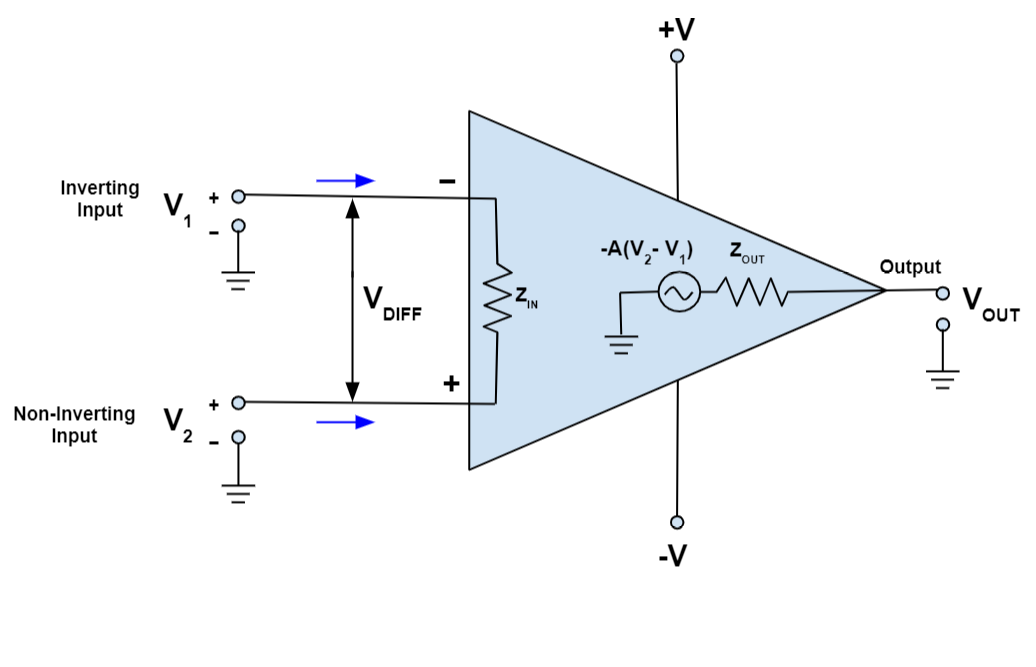
- Differential Amplifiers and Isolation Amplifiers: Differential amplifiers filter out common-mode noise by magnifying the difference between two input signals while ignoring noise that is common to both. Isolation amplifiers are a type of differential amplifier that provides further isolation by separating the analog and digital domains with inbuilt transformers or capacitors.
Filtering Techniques: Filtering is necessary to eliminate unwanted noise from signal lines and power supplies. Active components such as operational amplifiers or passive components such as resistors, capacitors, and inductors can be used to implement filters.
- Low-Pass Filters: In analog circuits, low-pass filters are frequently employed to reduce high-frequency noise produced by digital circuits. High-frequency noise is blocked by these filters, but low-frequency analog signals are allowed to pass through.
- Ferrite Beads: Ferrite beads are effective at reducing high-frequency noise in power and signal lines. They function as inductors at high frequencies, allowing DC and low-frequency signals to flow through while offering a high impedance to noise.
- Power Supply Filtering: Noise from the power source can be eliminated before it reaches sensitive analog circuits by using power supply filters, such as LC filters or Pi-filters. To ensure a clean power source, these filters are usually placed between the analog section and the power supply.
Grounding Techniques: Proper grounding is crucial in mixed signal designs to prevent noise from coupling through the ground plane.
- Star Grounding: Star grounding allows all ground connections to converge at a single point, decreasing the possibility of ground loops and noise coupling between analog and digital circuits. This technique works especially well in systems that have different power domains or multiple ground planes.
- Single-Point Ground Connection: The analog and digital ground planes are connected at a single point near the power supply, reducing the possibility of noise propagation between the two domains. It is important to choose this connection point carefully to avoid adding extra noise or compromising the integrity of the signal.
Power Supply Design: For both analog and digital circuits in mixed signal systems, a steady and noise-free power supply is crucial.
- Separate Power Domains: Separate power supplies for the analog and digital sections can help prevent noise from impacting the analog circuits. When separate supplies are not an option, thorough decoupling and filtering of the shared power supply is required.
- Low-Dropout Regulators (LDOs): LDOs are frequently employed in mixed signal designs to give clean, reliable power to sensitive analog circuits. They can filter out high-frequency noise from the digital power supply, guaranteeing that the analog circuits receive noise-free power.
Practical Considerations
Design Trade-offs: In mixed signal designs, isolation and noise reduction are essential, but they frequently come with trade-offs in terms of performance, complexity, and cost. For instance, including isolation components such as optical isolators or transformers increases the design's size and cost. Similar to this, adding layers or using more complex routing to optimize PCB layout for noise reduction can impact cost and manufacturing feasibility.
Simulation and Modeling: Before physical prototyping, simulation tools that simulate both analog and digital behavior are crucial for anticipating noise issues and evaluating the efficacy of isolation approaches. Designers can detect and fix any issues early in the design process by mixed signal simulation to examine noise coupling, signal integrity, and grounding issues.
Prototyping and Testing: Extensive testing is necessary when the design is finished to ensure that isolation and noise issues have been sufficiently resolved. This includes measuring EMI, power supply noise, and signal integrity in the finalized product, as well as testing under a variety of operating conditions to confirm that the design works reliably in real-world scenarios.
Practical Solutions for Signal and Power Integrity
Maintaining signal and power integrity is crucial for reliable operation and peak performance in mixed signal systems, which include both analog and digital circuits. While power integrity emphasizes providing a steady and noise-free power supply to all components, signal integrity relates to the quality and fidelity of the signals transmitted within a system. Noise coupling, signal deterioration, and power supply variations are all issues that might arise when high-speed digital signals and sensitive analog circuits exist together. With an emphasis on techniques that improve signal and power integrity in mixed signal designs, this section explores practical solutions to these challenges.
Signal Integrity Solutions
Optimized PCB Layout: In mixed signal systems, the printed circuit board's (PCB) layout plays a crucial role in preserving signal integrity. Effective PCB layout techniques can improve overall signal quality, reduce noise coupling, and minimize signal reflections.
- Controlled Impedance Traces: Controlled impedance traces are necessary for high-speed digital signals in order to avoid reflections and preserve signal integrity. This entails designing the trace width, spacing, and layer stack-up to achieve the appropriate impedance, which is usually 50 ohms for single-ended signals or 100 ohms for differential pairs.
- Differential Signaling: Differential signaling is a technique for improving signal integrity, particularly in noisy environments. Differential signaling enhances noise immunity by transmitting signals as complementary pairs, which lessens vulnerability to common-mode noise. This technique works especially well with high-speed data lines, such as those used in communication interfaces.
- Minimizing Crosstalk: Crosstalk occurs when signals from adjacent traces or wires interfere with one another. In order to reduce crosstalk, designers should employ guard traces or ground planes to protect sensitive analog signals from noisy digital signals, route high-speed signals on different layers, and increase the spacing between parallel traces.
- Short Trace Lengths: Minimizing trace lengths lowers the possibility of signal deterioration due to transmission line effects such as delay, attenuation, and reflections. This is particularly crucial for high-frequency signals since longer traces might act as antennas, picking up interference and radiating noise.
Signal Termination: Maintaining signal integrity and preventing signal reflections rely upon proper signal termination. In mixed-signal designs, several termination techniques are frequently employed:
- Parallel Termination: To absorb reflected signals and prevent them from bouncing back along the trace, a resistor that matches the trace's characteristic impedance is placed at the end of the signal trace.
- Series Termination: A resistor is placed at the signal trace's source end. This technique minimizes reflections without adding excessive load on the driver by lowering the signal's amplitude and slowing its rise time.
- Thevenin Termination: To match the impedance and stabilize the signal at a specific voltage level, pull-up and pull-down resistors are used in combination. Logic circuits and bidirectional buses frequently employ this technique.
Figure 26: Series trace termination
Figure 27: Thevenin trace termination
Shielding and Guard Traces: Shielding is the process of separating the analog and digital components of a PCB with a conductive barrier, such as a ground plane or metal shield, to reduce electromagnetic interference (EMI). In order to absorb and redirect noise away from crucial circuits, guard traces are grounded traces that are placed adjacent to sensitive signal lines.
- Ground Planes: Ground planes provide low-impedance return paths for signals, lowering the possibility of noise coupling and increasing signal integrity. To avoid ground loops, it is often beneficial to employ separate ground planes for the analog and digital sections of mixed signal designs, which are joined at a single point.
- Guard Traces: Guard traces serve as a barrier between sensitive and noisy traces, lowering the chance of interference by grounding these traces and absorbing noise.
Power Integrity Solutions
Dedicated Power Supply Domains: One of the most effective methods to ensure power integrity in mixed signal systems is to use dedicated power supply domains for the analog and digital sections. By using this method, the noise produced by digital circuits cannot impact analog circuits.
- Separate Regulators: The use of separate low-dropout regulators (LDOs) for the analog and digital sections ensures that each receives a consistent, noise-free power supply. In particular, analog circuits benefit from LDOs' clean, low-noise output.
- Power Plane Segmentation: Segmenting the power planes for the analog and digital sections helps to isolate noise and decreases the possibility of power supply ripple affecting sensitive analog circuits. To maintain a common reference voltage, these planes can be coupled at a single point close to the power source.
Decoupling and Bypass Capacitors: Capacitors for decoupling and bypassing are crucial for stabilizing the power supply and filtering out high-frequency noise. Choosing and placing these capacitors correctly is essential to preserving power integrity.
- Decoupling Capacitors: Decoupling capacitors, which are placed near the power pins of integrated circuits, filter out high-frequency noise from the power supply. To cover a wide frequency range, multiple capacitors with different values are frequently employed in parallel.
- Bypass Capacitors: A low-impedance path for high-frequency noise is provided by bypass capacitors, which are connected between the power supply and ground. These capacitors prevent noise from spreading throughout the system and assist in power supply voltage stability.
- Bulk Capacitors: Bulk capacitors are larger capacitors that are placed near the power source to store energy and regulate the supply voltage during load changes. They are especially significant in systems with high transient currents, such as those using fast-switching digital circuits.
Power Supply Filtering: Implementing filters on power supply lines reduces noise and ripple, ensuring that analog circuits receive a clean and consistent voltage.
- LC Filters: LC filters, which consist of capacitors and inductors, are effective at lowering power supply ripple and attenuating high-frequency noise. To further isolate noise, these filters can be placed near the power supply's input to the analog section.
- Ferrite Beads: Inductive components called Ferrite Beads provide high impedance at high frequencies, which effectively blocks high-frequency noise while permitting low-frequency and DC signals to flow through. To remove noise, they are frequently used in series with power supply lines.
Grounding Techniques: In mixed signal designs, proper grounding is crucial for maintaining both power and signal integrity. The probability of ground loops is decreased, and noise coupling is prevented by making sure the ground planes are correctly connected and well-designed.
Simulation and Analysis Tools: Simulation tools that model both signal and power integrity are extremely useful for detecting potential issues and optimizing designs before physical prototyping. By using these tools, designers can examine signal quality, power supply stability, and noise coupling, allowing them to spot and fix possible issues early in the design process.
- Signal Integrity Simulations: In order to reduce reflections and crosstalk, engineers can optimize trace routing, impedance matching, and termination schemes by simulating signal integrity in mixed signal designs using tools like SPICE and HyperLynx.
- Power Integrity Simulations: Power supply networks can be modeled using power integrity simulation tools, which enables designers to assess how decoupling, filtering, and power plane segmentation affect voltage stability and noise levels.
Prototyping and Testing: Once the design is complete, extensive testing is required to ensure that signal and power integrity issues have been addressed adequately. This includes measuring EMI, power supply noise, and signal integrity in the finalized product, as well as testing under a variety of operating conditions to confirm that the design works reliably in real-world scenarios.
Case Studies: Successful Integration in Complex Systems
There are many challenges with integrating analog and digital circuits in a single system, especially when it comes to preserving signal integrity, reducing noise, and guaranteeing reliable operation. Nevertheless, these challenges can be solved and successful integration in complex systems can be achieved with careful planning and innovative solutions. In order to demonstrate how theoretical concepts are used in real-world scenarios, this section includes case studies that highlight successful approaches to solving integration challenges in mixed signal environments.
Case Study 1: Mixed Signal Integration in a High-Performance Audio System
Digital processing units and analog components, such as amplifiers and analog-to-digital converters (ADCs), must be integrated for high-performance audio systems. Since these systems need to provide high-fidelity audio with little distortion or noise, signal integrity, and noise management are essential.
Challenges:
Signal Integrity: One major challenge was preserving the integrity of low-level analog audio signals while coexisting with high-speed digital signals. The overall sound quality could be lowered by any noise or distortion introduced to the analog domain.
Power Supply Noise: The system required a shared power supply for both analog and digital circuits, which raised concerns about power supply noise affecting delicate analog components.
Solutions:
Separate Ground Planes: The analog and digital sections of the design used separate ground planes, which were connected at a single point close to the power supply. By reducing noise coupling between the digital and analog domains, this method maintained the audio signals' integrity.
Power Supply Decoupling: To filter out high-frequency noise, decoupling capacitors were placed precisely near to the analog and digital ICs' power pins. A low-dropout regulator (LDO) supplied a clean, steady voltage to the analog section.
Shielding and Guard Traces: To properly shield the analog signal paths from digital noise, guard traces were incorporated into the PCB layout. To further lower the chance of interference, important analog components were placed away from noisy digital circuitry.
Differential Signaling: Differential signaling was applied to audio signal paths in order to increase noise immunity. This method-maintained signal integrity over lengthy traces and lessened the effect of common-mode noise.
Results:
The implemented solutions successfully reduced noise while maintaining signal integrity, resulting in a high-performance audio system with superior sound quality and low distortion. Noise coupling was reduced in particular by the careful design of the power supply and the separation of ground planes.
Case Study 2: Mixed Signal Design in a Medical Imaging System
Medical imaging devices, such as MRI and ultrasound equipment, rely on precise analog measurements mixed with powerful digital processing. These systems require high accuracy and reliability, which makes integrating analog and digital circuits challenging.
Challenges:
Noise Sensitivity: The analog front-end, which captures weak signals from sensors, was extremely sensitive to noise. Any disturbance from the digital processing unit can jeopardize the accuracy of the imaging data.
Isolation Requirements: To prevent noise from affecting the sensitive analog signals, the system needed to separate the analog measurement circuits from the digital processing circuits.
Solutions:
Optical Isolation: The analog measurement circuits were separated from the digital processing unit using optical isolators. By providing galvanic isolation, this method successfully prevented noise from propagating between the two domains.
Dedicated Power Supplies: The analog and digital sections, each with their own regulation and filtering stages, were powered by different suppliers. As a result, the digital circuits were powered separately, and the analog circuits were assured of a clean, noise-free power source.
Thermal Management: The analog components were isolated from heat-generating digital components in a thermally regulated environment to avoid thermal noise and drift. As a result, the analog measurements remained accurate and stable.
Shielded Enclosures: The analog circuits were enclosed in shielded enclosures, which protected them from external electromagnetic interference (EMI) and digital noise.
Results:
The accuracy of the analog measurements was preserved, and noise was successfully reduced by the use of optical isolation, dedicated power supplies, and shielding. The medical imaging system demonstrated high precision and reliability, which is critical for clinical applications.
Case Study 3: Mixed Signal Integration in Automotive Electronics
Analog sensors must be integrated with digital control and communication systems in order to operate modern automotive electronics, including infotainment systems and engine control units (ECUs). These systems operate under challenging conditions with high electrical noise levels and wide temperature ranges.
Challenges:
Harsh Operating Conditions: The automotive environment is prone to high levels of electrical noise, temperature fluctuations, and mechanical vibrations, all of which can have an impact on mixed signal system performance.
Signal Integrity in Communication Networks: Signal integrity had to be carefully managed when integrating multiple analog sensors with digital communication networks such as the Local Interconnect Network (LIN) and Controller Area Network (CAN).
Figure 28: Vehicle LIN bus
Solutions:
Robust Grounding Strategy: To reduce noise coupling and eliminate ground loops, a robust grounding strategy was implemented, which included the use of star grounding and multiple ground planes. Ground connections were carefully arranged to reduce impedance and assure reliable operation.
EMI Mitigation: In order to reduce noise produced by switching power supplies and other digital components, the design included EMI filters on both the power and signal lines. High-frequency noise in communication lines was filtered using common-mode chokes and ferrite beads.
Thermal and Vibration Management: Thermal and mechanical stress were considered when selecting and placing components. Heat dissipation was controlled by heat sinks and thermal vias, and delicate analog circuits were shielded by vibration-damping materials.
Differential Signaling and Shielded Cables: Long-distance communication between sensors and the ECU was facilitated by differential signaling, which lessened noise susceptibility. In the noisy automotive environment, shielded cables ensured reliable signal transmission by offering additional protection against electromagnetic interference.
Results:
With robust signal integrity and efficient noise reduction, the automotive electronics system operated reliably even under challenging conditions. Both analog and digital components operated as intended due to the use of differential signaling, EMI filters, and an adequate grounding strategy, which improved the vehicle's overall performance and safety.
直接登录
创建新帐号