Fundamental Principles of Power Circuit Design
An essential aspect of power electronics engineering is power circuit design, which includes creating circuits that efficiently and reliably convert, control, and supply electrical power. Following the fundamental principles of power circuit design is essential to achieving optimal performance, lifespan, and safety whether designing a simple power supply for a consumer gadget or a complex power converter for industrial applications. With a focus on efficiency, reliability, thermal management, and electromagnetic compatibility (EMC), this section examines the fundamental principles that guide the design of efficient power circuits.
Efficiency and Power Loss Minimization
Maximizing Efficiency: Efficiency has a direct impact on the circuit's overall performance, heat generation, and energy consumption, making it a crucial metric in power circuit design. Designers must reduce power losses that occur during electrical power conversion and distribution to optimize efficiency. This demands the careful selection of components with low conduction and switching losses, such as power transistors, diodes, and inductors. High-efficiency topologies, such synchronous rectifiers and resonant converters, are frequently used to lower losses and enhance the circuit's overall efficiency.
Switching Losses: Switching losses are a major source of inefficiency in many power circuits, especially those that use switch-mode power supplies (SMPS). When switching devices (such as MOSFETs or IGBTs) switch between their on and off states, these losses occur. Designers must carefully regulate the timing and switching speed to reduce switching losses. This ensures that the devices switch as fast as possible without experiencing excessive voltage or current overshoot. Additional techniques to lower switching losses and optimize efficiency include soft switching, which switches at zero voltage or zero current.
Conduction Losses: When current flows through resistive components in the circuit, such as a transistor's on-resistance or an inductor's winding resistance, conduction losses occur. These losses are especially important in high-current applications since they are proportional to the square of the current. Designers should select low-resistance components and make sure the circuit layout minimizes resistive paths in order to reduce conduction losses. Furthermore, the current can be distributed and individual conduction losses can be decreased by using parallel components, such as multiple transistors or diodes.
Reliability and Robustness
Thermal Management: Managing the heat generated by power losses is one of the main challenges in power circuit design. Overheating can lower reliability, impair component performance, and lead to failure. Effective thermal management entails designing the circuit to dissipate heat efficiently, utilizing techniques such as heat sinks, thermal vias in the PCB, and forced-air cooling. To maintain safe operating temperatures in high-power applications, advanced cooling techniques such as liquid cooling or thermoelectric coolers might be necessary.
Table 1: Comparison of cooling methods
| Thermal Management Technique | Heat Sinks | Thermal Vias | Forced-Air Cooling |
| Principle | Passive heat dissipation via increased surface area | Heat transfer through the PCB to layers beneath | Active cooling by forcing air over the heat source |
| Working Mechanism | Heat from the component is transferred to the fins of the heat sink and dissipated into the air | Heat generated by components is transferred to internal PCB layers via copper vias | A fan or blower moves air over components to carry away heat |
| Efficiency | High efficiency for localized cooling, dependent on size and material | Moderate efficiency, dependent on via size, density, and PCB design | High efficiency for components spread over a larger area |
| Space Requirements | Requires space above the component to fit the heat sink | Requires space within the PCB, typically in the form of vias | Requires space for a fan or blower, but fan size can vary |
| Effectiveness in High-Heat Environments | Effective for cooling high-heat components, especially when combined with thermal pads or interfaces | Suitable for moderate heat dissipation but less effective for high heat | Very effective when combined with fans and heat sinks in high heat conditions |
| Complexity of Implementation | Relatively simple but requires careful design to ensure good contact with the component | Requires design adjustments in the PCB layout and additional manufacturing steps | Requires additional components (fan, ducting) and careful airflow management |
Component Derating: Power circuit components should be derated, meaning operated below their maximum rated capacity, to guarantee reliability. Derating components including diodes, transistors, and capacitors extends their life and lowers the chances of breakdown from overvoltage, overcurrent, or thermal stress. For instance, a MOSFET's operational life can be increased and the junction temperature significantly decreased by running it at 70% of its maximum current rating.
Fault Tolerance and Protection: Fault tolerance must be considered while designing power circuits to guard against transients, overloads, and short circuits. This entails adding safeguards to the circuit and its connected devices, including fuses, current limiting circuits, and transient voltage suppressors. Feedback and monitoring systems that can detect and respond to abnormal conditions should also be included in the design. For example, thermal shutdown circuits, which turn off the power supply if the temperature rises above a safe threshold.

Electromagnetic Compatibility (EMC) and Noise Reduction
The capacity of an electronic system or device to operate as intended in its electromagnetic environment without producing or experiencing electromagnetic interference (EMI) is known as Electromagnetic Compatibility (EMC).
Minimizing Electromagnetic Interference (EMI): Significant electromagnetic interference (EMI) generated by power circuits can interfere with the operation of nearby electronic devices and breach regulatory standards. Designers must carefully control the circuit's layout and switching behavior to minimize EMI. This involves adopting snubber circuits to lessen voltage spikes, shielding and grounding techniques, and decreasing the loop area of high-current paths. Additionally, peak emissions can be decreased by spreading the energy over a larger frequency range through the use of spread spectrum techniques in switching frequency modulation.
Filtering and Decoupling: In power circuits, filtering is crucial for lowering radiated and conducted noise. Usually composed of capacitors and inductors, input and output filters are used to reduce high-frequency noise and make sure the circuit complies with EMC regulations.
Figure 1: Types of filters
Decoupling capacitors, when placed close to power supply pins, help to decrease voltage fluctuations and noise on the power rails, hence enhancing circuit stability and performance. The specific noise characteristics of the circuit and the necessary attenuation levels should guide the designers' selection of filter components.
Table 2:Conducted vs. radiated noise
| Aspect | Conducted Noise | Radiated Noise |
| Definition | Noise that travels along conductive paths (wires, cables, etc.) | Noise that spreads through the air as electromagnetic waves |
| Effect on Equipment | Can affect devices connected to the same power or signal lines | Can affect nearby equipment, often by induction or coupling |
| Primary Sources | Power supplies, inverters, motors, cables, and connectors | High-speed circuits, switching devices, wireless transmitters |
| Mitigation Techniques | Installation of filters, use of shielded cables, better grounding and layout design | Use of shielding enclosures, proper layout, antennas design, and compliance with radiation limits |
| Impact on System Performance | Can cause voltage spikes, signal degradation, or malfunctions in sensitive equipment | Can cause loss of signal integrity, interference with communications, or even hardware malfunction |
PCB Layout Considerations for EMC: The layout of the printed circuit board (PCB) is essential for obtaining optimum EMC performance. For high-current and high-frequency paths, designers should give priority to short, direct traces to minimize parasitic capacitance and inductance. In order to give currents a low-impedance return path, ground planes should be unbroken and continuous. Additionally, crosstalk and noise coupling between various circuit sections can be reduced by proper component placement and signal trace routing.
Scalability and Flexibility
Modular Design: Designing power circuits with scalability and flexibility in mind facilitates simpler adaption to various power levels or configurations. Modular design approaches entail developing standardized power modules that can be combined or scaled to meet the needs of different applications. This approach speeds up new product launches and streamlines design, testing, and maintenance. To provide different output voltages or currents, a modular power supply system, for example, might utilize interchangeable converter modules that can be configured in parallel or series.
Future-Proofing: It is essential to design power circuits that can be updated to meet future requirements in a rapidly evolving technological landscape. This could entail adding programmable or adjustable components that can be updated or reconfigured via software, such as digital controllers or adjustable regulators. Furthermore, extending the circuit's useful life and accommodating future technological improvements can be achieved by designing with adequate overhead in power ratings and including provisions for future upgrades, such as additional cooling or improved filtering.
Standard Methodologies for Efficient and Robust Design
Designing power converters and control systems in power electronics requires striking an equilibrium between robustness, efficiency, and reliability. Standardized methodologies that direct engineers in developing designs that satisfy performance standards while lowering the risk of failure are used to accomplish these objectives. This section explores the fundamental techniques required to develop reliable and efficient power electronics designs, with an emphasis on design procedures, modeling and simulation, prototyping, and iterative optimization.
Systematic Design Process
Top-Down Design Approach: The top-down design technique is a systematic methodology that starts with a high-level definition of system requirements and gradually refines the design into detailed subsystems and components. This approach lowers the possibility of integration issues later in the design process by ensuring that the overall system architecture is clearly specified before focusing on individual components. Engineers can make well-informed decisions regarding trade-offs between complexity, cost, and performance at each stage of the design process by beginning with the end goal in mind.
Figure 2: Top-down approach
Requirement Specification: Clearly defining the system requirements, including performance metrics, environmental conditions, regulatory compliance, and financial constraints is essential at the start of the design process. These specifications assist guarantee that the final product fulfills its intended function and forms the foundation for all succeeding design decisions. Input and output parameters, efficiency goals, thermal limits, and any other important factors that will affect the design should all be covered in detail in the specifications.
Design Partitioning and Modularity: A key strategy for guaranteeing robustness and flexibility is breaking the entire design up into smaller, more manageable subsystems or modules. The modular design makes it easy to test, debug, and upgrade in the future. The overall architecture can be made simpler by developing and validating each module independently. For instance, the power stage, control circuit, and thermal management system of a power converter can be designed as independent modules with specific interfaces to guarantee smooth integration.
Design for Manufacturability (DFM): Ensuring that a design can be manufactured at scale is an important part of robust design. In order to prevent issues such as high production costs, low yield, or challenging assembly, DFM considers the capabilities and constraints of manufacturing processes at the design phase. Choosing easily accessible components, designing PCB layouts that work with automated assembly procedures, and reducing the need for manual adjustments or calibrations are all part of this methodology.
Modeling and Simulation
Behavioral Modeling: Accurate models of the power converter and its control system must be created before committing to a physical prototype. Behavioral modeling entails constructing mathematical representations of the system's components and interactions. Before hardware is built, these models can be used to identify potential issues, forecast how well the system will function under various operating conditions, and optimize the design. Power electronics circuits and control systems are frequently modeled using programs like MATLAB/Simulink, SPICE, and PLECS.
Simulation-Based Verification: Simulation is used to check the design against the requirements after a behavioral model has been developed. Without running the risk of damaging physical components, engineers can use simulation to test how the system will react to a variety of scenarios, such as load fluctuations, component variations, and transient conditions. Engineers can spot and fix potential reliability issues early in the design phase by simulating the design under the worst-case conditions. Furthermore, simulation sheds light on the system's dynamic behavior, including transient response and stability margins, both of which are essential for reliable operation.
Thermal and Electromagnetic Analysis: Thermal and electromagnetic analysis, in addition to electrical performance, are crucial for designing reliable power electronics. Through the identification of hotspots and the prediction of temperature distributions throughout the circuit, thermal simulations aid in the design of PCB layouts, cooling systems, and heat sinks. Electromagnetic simulations, such as those performed with finite element analysis (FEA) tools, evaluate the impact of electromagnetic interference (EMI) and assure EMC compliance. Designing systems that can function reliably in real-world conditions requires these analysis.
Prototyping and Testing
Iterative Prototyping: Prototyping is an iterative process in which different versions of a design are created, tested, and perfected. The initial prototype, often known as a proof-of-concept, serves to illustrate basic functionality and validate the core design decisions. Based on testing results, subsequent prototypes contain improvements, with each iteration resolving issues and enhancing performance. Iterative prototyping lowers the possibility of expensive redesigns at the end of the development process by enabling engineers to gradually converge to a final design that satisfies all specifications.
Hardware-in-the-Loop (HIL) Testing: A methodology called hardware-in-the-loop (HIL) testing uses both simulation and real hardware to test the control system in a realistic environment. HIL testing involves simulating the rest of the system, including the power stage, in real time while implementing the control algorithms on real hardware, such as a microcontroller or DSP. This method eliminates the need to build a full physical prototype and enables comprehensive testing of the control system under a variety of operational conditions. HIL testing is very useful for validating control algorithms and verifying that they work as intended in the final system.
Figure 3: Hardware-in-the-loop testing
Environmental and Stress Testing: Power electronics designs must be evaluated in the same conditions as they will be used in the real world in order to guarantee robustness. This covers vibration testing, thermal cycling, and exposure to dust, humidity, and other contaminants. Stress testing, which involves exposing the system to conditions outside of its normal operating range, helps find potential failure modes and guarantees that the design is resilient to unforeseen conditions like component failures or power surges. Stress and environmental testing are essential for confirming that the design satisfies safety and reliability standards.
Iterative Optimization and Refinement
Performance Tuning: To maximize performance, the design frequently needs to be adjusted after initial testing. To minimize parasitic effects, this process may involve adjusting component values, refining control algorithms, or enhancing the layout. Performance tuning is an iterative process that involves evaluating each adjustment to determine how it affects the overall performance of the system. The objective is to meet all performance goals while striking the best possible balance between cost, efficiency, and reliability.
Feedback from Testing and Field Data: Component tolerances, environmental changes, and unanticipated system interactions are some of the reasons why real-world performance can diverge from simulations. Finding areas where the design might be enhanced requires gathering feedback from early field deployments and testing. Engineers can make data-driven decisions because of this feedback loop, modifying the design to improve user experience, performance, and reliability. The development of reliable and efficient power electronics that function well in a variety of applications requires constant improvement based on field data.
Documentation and Knowledge Transfer: Documenting all decisions, test results, and lessons learned is crucial during the design process. Comprehensive documentation helps transfer knowledge within the design team and to future projects, ensuring that valuable insights and methodologies are preserved and utilized. Design specifications, simulation models, test procedures, test results, and any modifications to the initial plan are all included in this documentation. Proper documentation helps the design organization succeed in the long term and promotes the standardization of design practices.
Importance of Component Selection and Placement
The efficiency, reliability, and overall performance of the final product are all influenced by the careful component placement and selection in power converter and control system design. In power conversion processes, components including capacitors, inductors, transistors, and diodes are essential, and the behavior of the circuit is directly influenced by their characteristics. Additionally, the physical placement of these components on the printed circuit board (PCB) influences electromagnetic compatibility (EMC), thermal management, and electrical performance. This section explores the significance of component placement and selection in power electronics design, highlighting the ways in which these decisions affect the success and efficiency of the design.
Importance of Component Selection
Electrical Performance: A power converter's performance and efficiency are directly impacted by the electrical characteristics of its components, including resistance, capacitance, inductance, and switching speed. In a switching power supply, for instance, choosing a MOSFET with low on-resistance is essential to minimize conduction losses. Similarly, ripple voltage can be decreased, and filtering efficiency can be improved by selecting capacitors with low equivalent series resistance (ESR). To make sure that every component satisfies the specific requirements of the circuit, engineers must carefully review component datasheets and performance parameters, accounting for factors including voltage ratings, current ratings, and thermal performance.
Reliability and Longevity: The durability and quality of a power converter's components have a significant impact on its reliability. Particularly in extreme environmental conditions, components that operate near their maximum ratings are more likely to fail prematurely. To increase reliability and prolong the circuit's lifespan, engineers frequently use components with a safety margin known as derating. To prevent breakdowns, for example, capacitors should be selected with voltage ratings far higher than the anticipated operating voltage. To further reduce the chance of failures, components from reputable manufacturers with established reliability and quality records are preferred.
Thermal Management: The thermal performance of components is an important concern in power electronics design. During operation, power components such as MOSFETs, diodes, and inductors produce heat, which needs to be efficiently managed to avoid thermal runaway and guarantee long-term reliability. It is crucial to choose components with advantageous thermal characteristics, such as high maximum junction temperatures and low thermal resistance. To improve heat dissipation and maintain acceptable operating temperatures, the component selection procedure should also consider the use of heat sinks, thermal pads, and other cooling methods.
Component Availability and Cost: Practical considerations such as component availability and cost are crucial in the selection process, in addition to performance and reliability. Engineers have to strike a balance between meeting production timelines and budget constraints and the demand for high-performance components. To prevent supply chain interruptions, components with multiple sources and wide availability are preferred. Cost-effective components that still fulfill the required performance criteria also contribute to the product's overall cost reduction, making it more competitive in the market.
Importance of Component Placement
Minimizing Parasitic Effects: The physical placement of components on the PCB is critical in reducing parasitic effects including inductance and capacitance, which can affect circuit performance. In a switching power supply, for instance, power transistors, diodes, and associated passive components should be placed to minimize the loop area of high-current paths in order to lower parasitic inductance.This reduces the electromagnetic interference (EMI), and voltage spikes produced during switching transitions. Similarly, decoupling capacitors near integrated circuit power pins helps reduce parasitic resistance and inductance, increasing the efficiency of noise suppression.
Optimizing Signal Integrity: For control signals, particularly sensitive or high-speed analog signals, to be delivered precisely and free from noise interference or distortion, signal integrity is essential. By reducing trace lengths, avoiding crosstalk, and offering sufficient grounding, proper component placement contributes to signal integrity. For example, the accuracy of analog signal processing can be increased and interference can be decreased by placing analog components, such as operational amplifiers, away from noisy digital or power circuitry. Signal integrity can also be further improved by eliminating sharp turns in traces, which are points of high impedance, and routing high-frequency signals over continuous ground planes.
Thermal Management Through Layout: Component placement influences thermal performance in the same way that component selection does. Placing components that generate heat in locations where heat can be dissipated efficiently is essential to effective thermal management. Power transistors or regulators, for example, can be placed near the PCB's edge to facilitate the attachment of heat sinks that dissipate heat into the surrounding environment. Thermal vias can be used to transfer heat from the top layers of the PCB to the inner or bottom layers, where it can be easily managed, and components that produce significant heat should be separated to avoid localized hotspots.
Electromagnetic Compatibility (EMC): Achieving electromagnetic compatibility (EMC) requires careful consideration of component placement. Excessive EMI from improper placement might interfere with nearby electronic devices or lead the circuit to fail EMC testing. Placing high-frequency switching components, including MOSFETs and drivers, next to one another minimizes radiated electromagnetic interference (EMI) by reducing the loop area of high-frequency currents. Furthermore, placing filter components including inductors and capacitors close to the power input or output terminals helps in reducing conducted EMI, and enhancing the circuit's overall EMC performance.
Design for Manufacturability (DFM) and Assembly: Beyond electrical performance, component placement influences the PCB's manufacturability and ease of assembly. The arrangement of components should guarantee reliable soldering and enable automated assembly procedures, such as pick-and-place machines. For instance, orienting surface-mount components consistently helps accelerate assembly and lower error. Test points, connectors, and other interface components should be placed appropriately, and essential components should be placed to facilitate testing and debugging.
Strategies for Optimal Component Placement
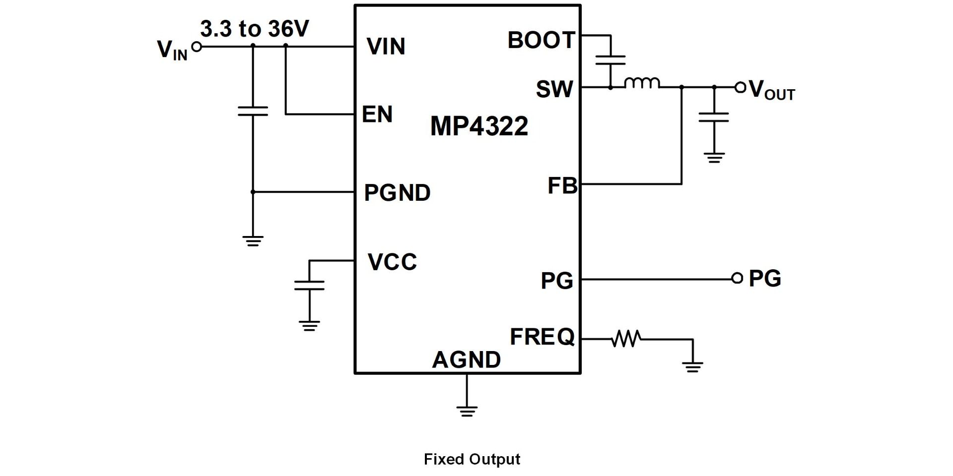
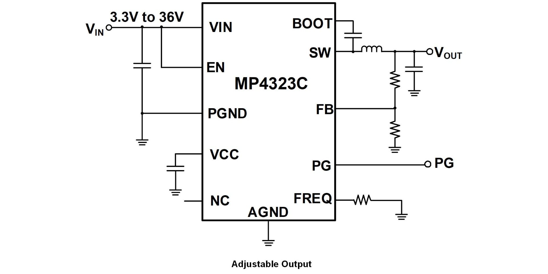
Prioritizing Critical Paths: Critical paths in power converter design, such as those carrying high current or high-frequency signals, should be prioritized in component placement. To reduce parasite effects and enhance efficiency, these paths should be as short and direct as possible. For instance, in order to minimize switching noise and increase efficiency, the MOSFET, inductor, and output capacitor should be placed as close together as possible in a buck converter.
Figure 4: Buck converter circuit
Grounding and Decoupling: For power electronics to operate steadily and reduce noise, proper grounding and decoupling are crucial. To reduce ground loops, components that require stable ground references, including low-noise amplifiers or analog sensors, should be placed close to the ground plane. To provide efficient noise filtering, decoupling capacitors should be placed as close as possible to the ICs' power pins. In order to prevent ground loops, which can cause noise and interfere with the circuit's operation, the placement of multiple ground points should also be carefully considered.
Zoning and Partitioning: The process of zoning entails dividing the PCB into several sections according to its functions, such as digital, analog, and power zones. Engineers can enhance overall circuit performance and minimize interference between different signal types by grouping similar components together. For instance, it is less likely that digital noise can impact delicate analog signals when digital components, like memory chips and microcontrollers, are kept separate from power components. Additionally, during the development process, testing and troubleshooting are made easier by dividing the PCB into zones.
Figure 5: PCB zoning
Thermal Considerations: To guarantee that heat is efficiently managed, thermal considerations should be included when placing components. Heat-sensitive components, including electrolytic capacitors or temperature-sensitive integrated circuits, should not be placed near heat sources; instead, components that produce significant heat should be placed in locations with airflow. Potential hotspots can be found and component placement can be guided by using thermal simulation tools to maximize heat dissipation and maintain safe operating temperatures.
Best Practices for PCB Layout in Power Electronics
A crucial component of power electronics design, the printed circuit board (PCB) layout has a direct impact on the end product's reliability, performance, and efficiency. Optimal electrical performance, efficient thermal management, and adherence to electromagnetic compatibility (EMC) standards are all guaranteed by a meticulously designed PCB layout. The best practices for PCB layout in power electronics are explored in this section, with an emphasis on important considerations including trace routing, grounding, thermal management, and EMI minimization.
Trace Routing
Minimizing Parasitic Inductance and Capacitance: High current levels and high frequency switching in power electronics can produce large amounts of parasitic capacitance and inductance, which can impair circuit performance. Traces that carry high currents or switch rapidly should be kept as short and wide as feasible to reduce these parasitic effects. This minimizes voltage drops and boosts overall efficiency by lowering the traces' resistance and inductance. Traces should also be routed directly between components to prevent unwanted inductance from being introduced by loops or detours.
Optimizing Power and Ground Planes: Ground and power planes are essential for reducing voltage drops and offering low-impedance paths for current flow. For steady functioning and noise reduction, a continuous, unbroken ground plane is necessary. To minimize electromagnetic coupling between layers and establish a low-inductance path, the power plane should be placed directly next to the ground plane. It is also crucial to keep high-current traces as close to the power and ground planes as possible to minimize loop area, which aids in reducing radiated EMI.
Figure 6: Power and ground planes in a PCB
Routing Critical Signals: To guarantee signal integrity and reliable operation, critical signals, such as gate drive signals in a switching power supply need to be carefully routed. To avoid coupling noise into the control signals, these signals should be routed as short as possible and placed away from noisy power traces. For feedback loops, differential signals should be routed as closely matched pairs in order to reduce noise and signal distortion. To avoid interference, digital and sensitive analog signals should be routed independently.
Controlled Impedance and Signal Integrity: Maintaining controlled impedance in high-frequency designs is critical to signal integrity. This involves developing traces with consistent width and spacing in order to attain the requisite characteristic impedance, which is frequently necessary for RF circuits or high-speed digital signals. Careful stack-up design, in which the trace width, PCB material, and layer spacing are adjusted to match the desired impedance, can result in controlled impedance. The PCB layout can be verified to make sure it satisfies the required impedance and signal quality standards using signal integrity analysis tools.
Grounding Techniques
Single-Point Grounding vs. Multipoint Grounding: A fundamental aspect of PCB design is grounding, especially in power electronics where precise signal processing and noise reduction relies on stable ground references. Low-frequency designs often use single-point grounding to minimize ground loops, in which all ground connections converge at a single point. However, multipoint grounding, in which the ground plane is distributed throughout the PCB, is more successful in lowering noise and enhancing EMC performance in high-frequency or high-power designs.
Table 3: Single-point vs. multipoint grounding
| Aspect | Single-Point Grounding | Multipoint Grounding |
| Definition | All system components are connected to a single ground point | Multiple ground points are connected to a common ground system |
| Application | Common in small systems or low-frequency applications | Typically used in larger or high-frequency systems |
| Grounding Resistance | Generally results in a higher overall grounding resistance | Can achieve lower overall grounding resistance by using multiple paths |
| Reliability | Less reliable in large systems with many components, as the single point may become a weak link | More reliable in larger systems, as the failure of one grounding point does not affect the entire system |
| Noise Susceptibility | Less susceptible to noise and electromagnetic interference (EMI) due to the shared reference point | Higher susceptibility to EMI, especially if ground loops form or the ground network is not properly designed |
| Design and Safety Considerations | Can result in safety issues if the grounding point becomes faulty, affecting the whole system | Provides better fault tolerance and safety by distributing grounding across multiple points, reducing the impact of a single failure |
Ground Plane Segmentation: Segmenting the ground plane may be required in some designs in order to separate sensitive analog or control circuitry from noisy circuit segments. This is especially crucial in mixed-signal designs since low-level analog signals can be affected by digital switching noise. To prevent ground loops, ground plane segmentation should be carefully planned. Connections between segmented ground planes should be made at a single point, usually via a controlled impedance trace or a low-impedance path such as a ferrite bead.
Decoupling and Bypass Capacitors: Decoupling capacitors are crucial for filtering out high-frequency noise and stabilizing power supply voltages; they should be placed as close to integrated circuits' (ICs') power pins as possible to reduce the connection's inductance. To cover a wide range of frequencies, multiple capacitors of different values are frequently used in parallel; smaller capacitors handle high-frequency noise, while bigger capacitors handle low-frequency noise. In order to minimize voltage fluctuations and offer a local reservoir of charge, bypass capacitors should also be placed close to high-speed switching devices.
Thermal Management
Thermal Via Arrays: In power electronics, managing heat is essential to maintaining the circuit's reliability and long lifespan. Thermal vias, which are vertical connections that transfer heat from the PCB's top layers to its inner or bottom layers, are an effective technique for improving heat dissipation. Arrays of thermal vias are commonly placed beneath heat-producing components, such as voltage regulators or power transistors, to efficiently transfer heat from the component to the PCB, where it can be dissipated over a larger area.
Figure 7: Thermal via arrays
Copper Pour and Heat Sinks: To disperse heat from hot components and lower the overall thermal resistance, copper pours, or large areas of copper on the PCB, can be utilized. To take advantage of the entire thermal capacity of the PCB, these copper areas ought to be connected to the ground or power planes. For extra cooling, heat sinks can also be installed directly on components or on the PCB. Heat sinks and other cooling mechanisms should be given enough room when designing the PCB layout to avoid interfering with other components or traces.
Component Placement for Optimal Cooling: The PCB's thermal performance can be significantly impacted by the components' placement. Components that produce heat should be separated to avoid hotspots and to provide enough airflow. High thermal load components should be placed close to the PCB's edge or where cooling resources are most readily accessible, such as close to fans or enclosure vents. Heat-generating components can be placed on different layers of multilayer PCBs to assist distribute the thermal load more equally throughout the board.
Minimizing Electromagnetic Interference (EMI)
Shielding and Isolation: One efficient method to lower EMI in power electronics is through shielding. To prevent external interference, sensitive sections of the circuit, such as analog inputs or low-level signal paths, can be shielded with metal shields or grounded copper pour areas. The high-frequency noise produced by switching devices can also be contained by shielding, which prevents it from coupling into other circuits. In circuits that need galvanic isolation, isolation techniques like employing transformers or optocouplers can also aid in reducing EMI and breaking ground loops.
Snubber Circuits and Damping Resistors: In power electronics, Snubber circuits are frequently used to mitigate voltage spikes brought on by inductive load switching. In order to absorb the energy of the spike and prevent it from radiating as EMI, these circuits usually include a resistor and capacitor placed across a switching device, such as a MOSFET or relay. In signal lines, damping resistors can also be employed to minimize reflections and ringing, which are common causes of high-frequency electromagnetic interference (EMI). These components must be placed and designed precisely to reduce EMI and guarantee steady operation.
Figure 8: Snubber circuit
Filter Design and Placement: Unwanted high-frequency noise on power and signal lines is attenuated using EMI filters. Usually, these filters consist of capacitors and inductors arranged in LC or Pi filter configurations. Importantly, these filters should be placed as close to the source of the noise or the PCB's point of entry or exit as possible. For instance, power supplies' input and output filters must be placed close to the connectors to stop noise from getting into or out of the PCB. Carefully routing traces and making sure filter components are grounded properly can increase the effectiveness of these filters.
Design for Manufacturability (DFM) and Testability
Component Orientation and Placement for Assembly: Manufacturability must be considered when designing the PCB layout in order to lower production costs and increase yield. Components should be oriented consistently to make assembly easier, especially for surface-mount devices (SMDs). There should be enough space between components to allow automated soldering and placement without causing misalignment or shorts. Crucial components should also be easily accessible for testing and inspection so that any issues can be promptly found and fixed all during manufacturing.
Test Points and Debugging Access: Including test points in the PCB layout is critical for conducting extensive testing and debugging throughout development and production. To facilitate easy probing and measurement, test points should be placed on essential signal lines, such as power rails, control signals, and communication interfaces. To allow for testing equipment without interfering with other components, these test points should be properly marked and spaced. Access to crucial circuit nodes is another aspect of designing for testability, which enables automated test equipment (ATE) or in-circuit testing (ICT) to confirm the PCB's operation.
直接登录
创建新帐号