Case Study 1: Digital Control of DC/DC converters
In power electronics, DC/DC converters are essential components that are frequently used to change the voltage of electrical power. These converters' performance, adaptability, and efficiency are improved by digital control techniques, which makes them appropriate for a range of applications including power supply, renewable energy systems, and electric vehicles. The application and benefits of digital control in DC/DC converters are explored in this case study.
Introduction to DC/DC Converters
Functionality:
Objective: Convert a direct current (DC) source from one voltage level to another by either stepping up (boost) or stepping down (buck) the voltage.
Applications: utilized in power supplies, electric vehicles, renewable energy systems, and battery-powered gadgets.
Types of DC/DC Converters:
Buck Converter: Lowers the output voltage by stepping down the input voltage.
Boost Converter: Increases the output voltage by stepping up the input voltage.
Buck-Boost Converter: Depending on the needs, the input voltage can be stepped up or down.
Digital Control of DC/DC Converters
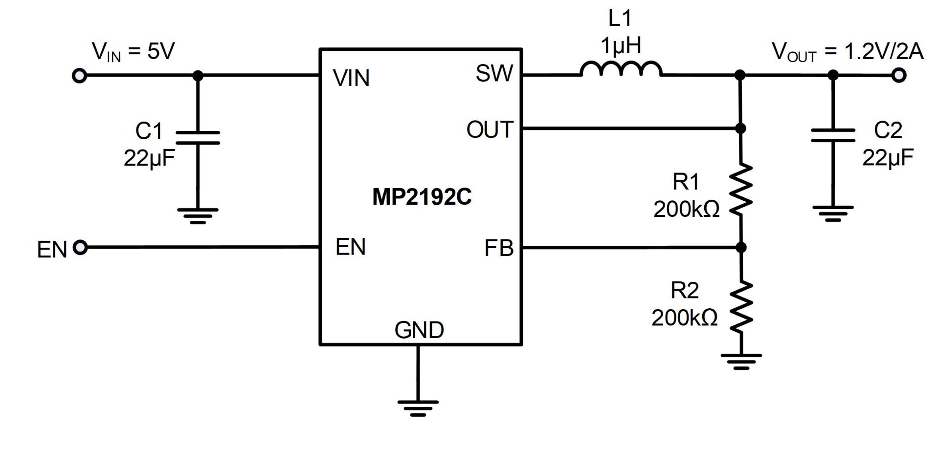
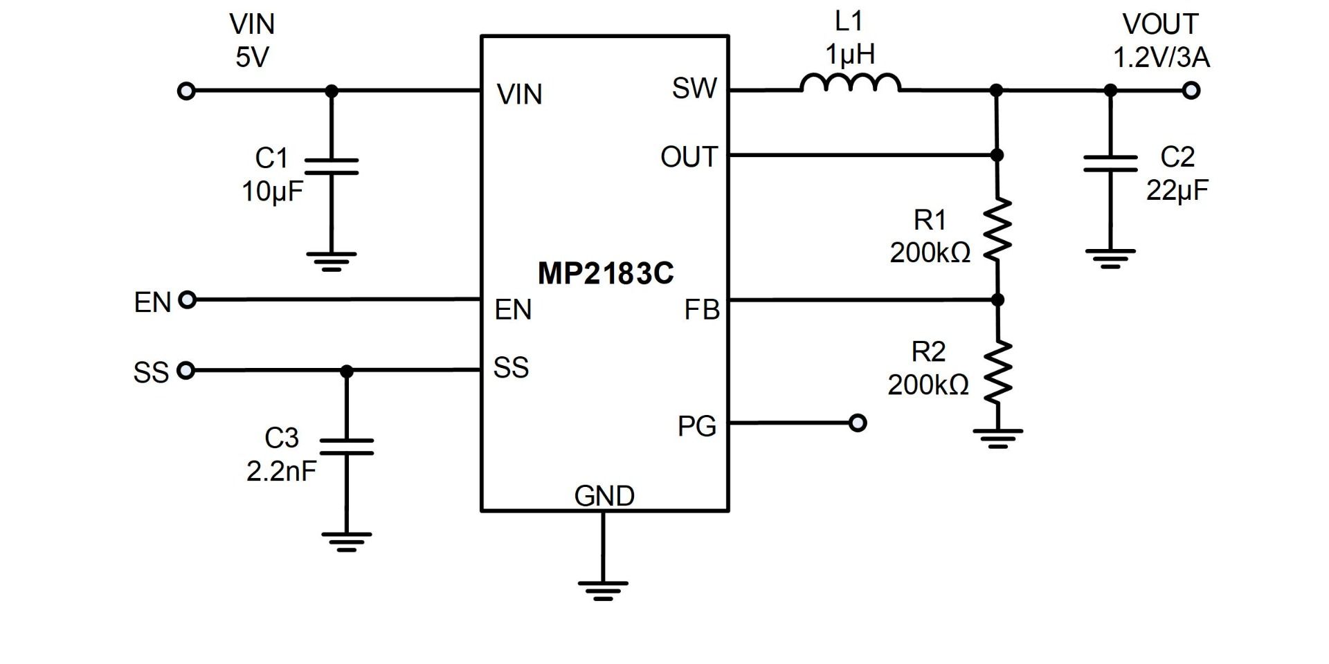
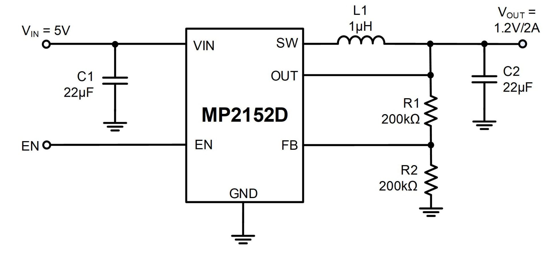
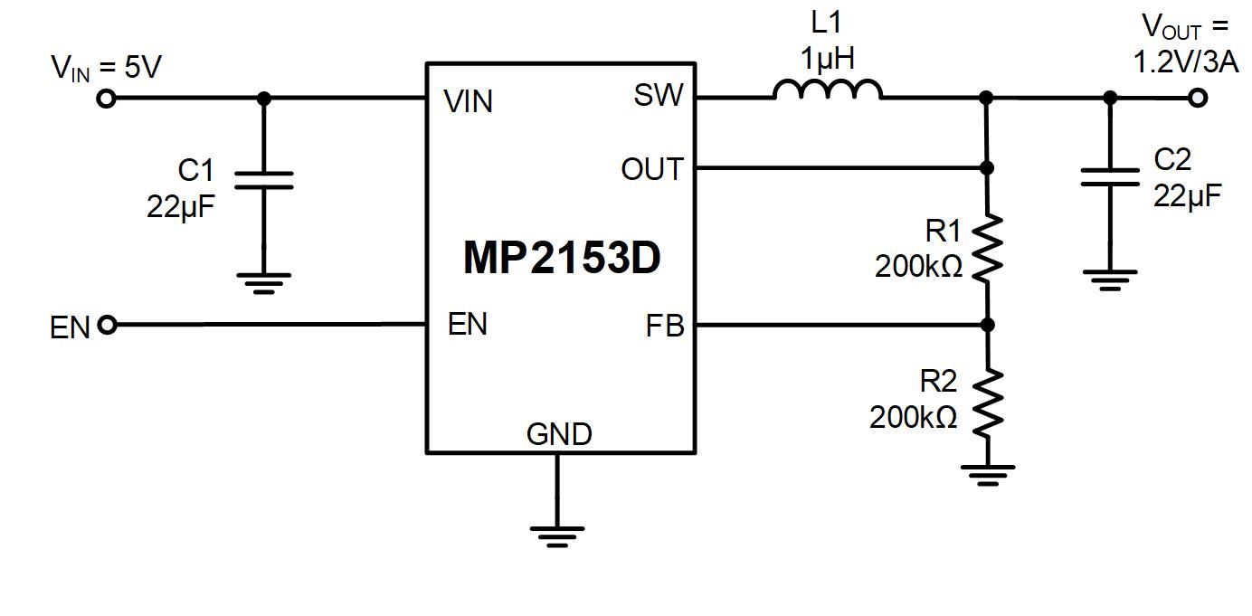
Digital control in DC/DC converters refers to the use of digital signal processors (DSPs) or microcontrollers (MCUs) to control the output voltage of the converter. Using feedback from the output voltage, the digital controller modifies the duty cycle of the switching transistor in the converter.
Advantages of Digital Control:
Precision and Flexibility: Complex control algorithms can be implemented with great precision and flexibility because of digital controllers.
Adaptability: Easily programmable to adjust to various needs and operational conditions.
Integration: Able to incorporate cutting-edge features including adaptive control, communication interfaces, and fault detection.
Implementation of Digital Control in a Buck Converter
System Description:
Components: Pulse Width Modulation (PWM) controller, microcontroller, buck converter, input voltage source, and feedback loop with voltage sensor.
Objective: Despite changes in input voltage and load conditions, maintain the output voltage constant.
Control Algorithm:
PID Controller: A popular option for controlling the output voltage by varying the PWM signal's duty cycle.
Implementation Steps:
Modeling: Develop a mathematical model of the buck converter incorporating the dynamics of the switching transistor, inductor, and capacitor.
Algorithm Development: Develop a PID control algorithm that uses the output voltage feedback to modify the PWM duty cycle.
Simulation: To validate the design and adjust the PID parameters, use MATLAB/Simulink to simulate the buck converter and PID control algorithm.
Microcontroller Programming: Implement the PID algorithm in C/C++ and deploy it on a microcontroller (such as the STM32).
Hardware Setup: Attach the voltage sensor for feedback and the microcontroller to the buck converter circuit.
Testing and Optimization:
Initial Testing: Make sure that the output voltage stabilizes at the intended setpoint by verifying the control algorithm's basic functionality.
Parameter Tuning: Adjust the PID parameters to minimize overshoot, minimize steady-state error, and maximize the transient response.
Performance Evaluation: To make sure the system is stable and robust, test it under different input voltage and load conditions.
Practical Example: Digital Control of a Boost Converter for Solar Applications
System Description:
Objective: To enhance power extraction from solar panels, use digital control to operate a boost converter in a solar power system.
Components: Maximum Power Point Tracking (MPPT) algorithm, boost converter, DSP (such as the TMS320 series), solar panel, and feedback loop with voltage and current sensors.
Control Algorithm:
MPPT Algorithm: Use an MPPT algorithm, like Perturb and Observe (P&O), to modify the duty cycle in order to optimize the solar panel's power generation.
Voltage Regulation: To manage the boost converter's output voltage, use a PID controller.
Implementation Steps:
Modeling: Design a model of the solar panel and boost converter that include the electrical dynamics and characteristics.
Algorithm Development: To maximize power extraction and manage the output voltage, design the MPPT and PID control algorithms.
Simulation: Validate the MPPT and voltage regulation algorithms by simulating the complete system using software tools.
DSP Programming: Implement the control algorithms in C/C++ and deploy them on the DSP.
Hardware Integration: Assemble the boost converter with the DSP and sensors to guarantee precise control and feedback.
Testing and Optimization:
Initial Testing: Check the PID controller's efficiency in regulating voltage and the MPPT algorithm's capacity to monitor the maximum power point.
Parameter Tuning: To maximize performance in a range of temperature and solar irradiation conditions, adjust the control parameters.
Performance Evaluation: To ensure reliable operation and optimal efficiency, test the system under real solar conditions.
Case Study 2: Digital Control of Grid-tied Converters
In order to efficiently transport energy from sources like solar panels or wind turbines to the electrical grid, grid-tied converters are crucial parts of renewable energy systems. These converters are essential to modern power systems because of their improved performance, reliability, and flexibility due to digital control techniques. The application and benefits of digital control in grid-tied converters are explored in this case study.
Introduction to Grid-Tied Converters
Functionality:
Objective: Transform renewable energy sources' DC power into AC power that can be fed to the electrical grid.
Applications: Utilized in wind turbines, solar power systems, and other renewable energy infrastructure.
Types of Grid-Tied Converters:
Single-Phase Inverters: Usually utilized in residential solar power systems, this device converts DC power to single-phase AC power.
Three-Phase Inverters: Utilized in wind farms and solar power plants for residential and commercial uses, converts DC power to three-phase AC power.
Digital Control of Grid-Tied Converters
In grid-tied converters, digital control refers to the use of digital signal processors (DSPs) or microcontrollers (MCUs) to regulate the conversion process and guarantee grid synchronization. Based on input from the power supply and the grid, the digital controller modifies the inverter's switching patterns.
Advantages of Digital Control:
Precision and Flexibility: Complex control algorithms can be implemented with great precision and flexibility due to digital controllers.
Grid Synchronization: Enhanced ability to align the output of the inverter with the voltage and frequency of the grid.
Fault Detection and Handling: Sophisticated features that improve system safety and reliability by identifying and addressing faults.
Implementation of Digital Control in a Single-Phase Inverter
System Description:
Components: Microcontroller, single-phase inverter, solar panels, DC/DC converter (to boost voltage), and grid interface with voltage and current sensors.
Objective: Convert solar panels' DC output to AC power and feed it into the grid whilst maintaining sync and optimizing efficiency.
Control Algorithm:
Phase-Locked Loop (PLL): Used for grid synchronization, which makes sure the frequency of the inverter's output corresponds to the frequency of the grid.
Pulse Width Modulation (PWM): Regulates the output voltage and current by controlling the switching components of the inverter.
Maximum Power Point Tracking (MPPT): Maximizes the solar panels' ability to extract power.
Implementation Steps:
Modeling: Create a mathematical model of the grid interface and the inverter, including the dynamics of the filters and switching devices.
Algorithm Development: Design the MPPT, PLL, and PWM algorithms to regulate the inverter's functioning.
Simulation: To validate the control algorithms and simulate the inverter system, use MATLAB/Simulink.
Microcontroller Programming: Use C/C++ to implement the control algorithms, then deploy them to a microcontroller (such as the STM32).
Hardware Setup: Connect the microcontroller and sensors for voltage and current feedback to the inverter circuit.
Testing and Optimization:
Initial Testing: Check the basic operation of the control algorithms to ensure the inverter synchronizes with the grid and regulates the output correctly.
Parameter Tuning: Fine-tune the control parameters to enhance efficiency, reduce harmonic distortion, and improve synchronization.
Performance Evaluation: To guarantee robustness and reliability, test the system under a range of grid conditions and solar irradiance levels.
Practical Example: Digital Control of a Three-Phase Inverter for Wind Turbines
System Description:
Objective: To convert variable DC power from a wind turbine system into steady AC power for the grid, use digital control for a three-phase inverter.
Components: Wind turbine, three-phase inverter, rectifier (to convert AC to DC), DSP (for example, the TMS320 series), and feedback loop with voltage and current sensors.
Control Algorithm:
Vector Control (Field-Oriented Control): Used to precisely regulate the output voltage and current by controlling the three-phase inverter.
Grid Synchronization: To synchronize the inverter output with the grid, use a PLL.
Power Management: Algorithms for controlling power flow, such as MPPT, which maximizes wind turbine power extraction.
Implementation Steps:
Modeling: Develop a model that incorporates the mechanical and electrical dynamics of a wind turbine and three-phase inverter.
Algorithm Development: Design vector control, algorithms for power management, PLL.
Simulation: To validate the control strategies and simulate the entire system, use software tools.
DSP Programming: Deploy the control algorithms to the DSP after implementing them in C/C++.
Hardware Integration: Accurate feedback and control are ensured by configuring the three-phase inverter with the DSP and sensors.
Testing and Optimization:
Laboratory Testing: In a controlled environment, simulate varying wind speeds and grid conditions to test the inverter control system.
Field Testing: In a real wind turbine installation, install the system and track its performance over time.
Optimization: Improve the control algorithms' efficiency, lower harmonic distortion, and guarantee steady functioning under a range of conditions.


直接登录
创建新帐号