Introduction to ADC Output Interfaces
An analog-to-digital converter’s (ADC) output interface is crucial to the overall conversion process since it acts as the channel for sending converted digital data to other system parts like memory, microcontrollers (MCUs), and digital signal processors. This section will examine the significance of output interfaces and the variables affecting the choice of an interface type.
Importance of Output Interfaces
The efficient and dependable transport of data from the ADC to the system's later stages depends heavily on output interfaces. They are extremely important in:
Data Integrity: This ensures that digital data is transmitted without mistakes or loss. Data corruption may occur as a result of an inadequately designed or poorly chosen interface.
System Synchronization: It is critical that data sampling and transmission be coordinated with other system elements in many applications. Often, the clock or timing signals required for this synchronization are provided by the output interface.
Throughput and Latency: The maximum sampling rate of the ADC and, consequently, the bandwidth of signals that may be reliably digitized, are influenced by the speed at which data is transferred through the output interface. The interface has an effect on data availability latency as well.
Power Consumption: The output interface can have a substantial impact on the system's overall power usage, particularly in battery-powered applications.
Scalability and Compatibility: The output interface may have an impact on how easily a system can be interfaced with or expanded upon by other parts and systems. As standards change, it might affect how long the system lasts.
Factors Affecting Choice of Interface
ADC output interface selection is influenced by a number of variables, such as:
Data Rate Requirements: While low-speed applications may choose to use simpler, less expensive interfaces, high-speed applications may require interfaces that can handle large data rates.
Complexity and Cost: Parallel interfaces could need more pins and complicated routing than serial interfaces, which can have an impact on price and needed board space
Cable Length and Environment: Due to their noise immunity, differential interfaces like low voltage differential signaling (LVDS) may be favored in systems where the ADC and receiving component are far away or in electrically loud surroundings.
Power Consumption: While mains-operated systems could permit higher power consumption, battery-operated systems frequently call for low-power interface .
Standardization and Compatibility: The interface to use may be determined by some standards set by the industry, or by the need to be compatible with already installed hardware or software .
Processing Overhead: The management of communication through some interfaces may require more significant processing overhead, which could affect system performance. .
Flexibility and Future-Proofing: It's crucial to take into account how potential system expansions or upgrades may change the requirements for the interface.
Parallel Interfaces
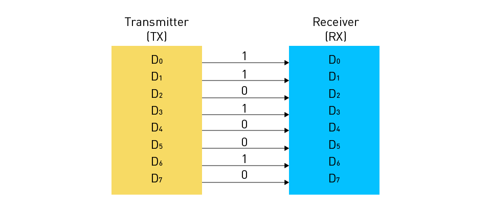
One of the more common ways to connect ADCs to other devices, like microprocessors or FPGAs, is through parallel connections. Parallel connections send many bits of data simultaneously over a number of data lines, as opposed to serial interfaces, which transmit data bit-by-bit across a single data line .

Figure 1: Parallel interface
Basic Operation
The ADC output word's bits are connected to their respective data lines through parallel interfaces. An 8-bit ADC for instance contains eight distinct data lines, each of which carries a single bit of information. The ADC transmits all bits concurrently across these lines to the connected device after the conversion is finished. Parallel interfaces typically have control lines, such as 'read,' 'write,' and 'enable,' that regulate the timing and direction of data flow in addition to data lines. A data-ready line may also be present to show when the data is ready to be read.
Timing Considerations
In parallel interfaces, timing is essential. All bits must reach the destination at the same time because data is carried across several lines, this is known as Data alignment. Data corruption can occur as a result of any timing error. Control signals must also be timed correctly in relation to data signals.
It is also necessary to take into account the propagation delay, which is the amount of time it takes for data to move from the ADC to the receiving device. Cable length, capacitance, and the electrical properties of the components all have an impact on the propagation delay.
The output of the ADC must also be stable for a long enough period of time for the receiving device to read it. The parallel interface's timing diagram contains vital details on how to time the data and control signals properly.
Advantages and Disadvantages
Advantages
- High Throughput: Parallel interfaces can achieve high data transmission speeds since several bits are sent simultaneously.
- Simple Data Processing: Data processing is made simpler because the entire data word is received by the receiving device at once.
Disadvantages
- Pin Count and Complexity: A lot of pins are needed for parallel interfaces (one for each piece of data), in addition to extra control lines. This may result in a greater physical size for the connector as well as higher routing complexity.
- Signal Integrity: As the data rate rises, maintaining signal integrity across all lines becomes more difficult. Timing skew can be caused by any mismatch in the electrical properties of the wires.
- Power Consumption: When driving signals on more lines, especially at high data rates, power consumption is frequently higher.
- Limited Cable Length: Parallel connections are frequently employed over small distances since longer-distance signals degrade over time.
In conclusion, applications where high throughput is essential and system design is not constrained by pin count, power consumption, or cable length are best suited for parallel interfaces. However, serial interfaces are frequently used for new designs due to the rising data rates demanded by contemporary applications and the drawbacks stated above.
Serial Interfaces
ADCs are connected to microcontrollers, microprocessors, or other digital systems via serial interfaces in contemporary systems. Serial interfaces send data sequentially, bit by bit, via a single or a small number of data lines, as opposed to parallel interfaces, which transport multiple bits simultaneously over different lines.

Figure: 2 Serial interface
Basic Operation
Data is transmitted via a communication channel one bit at a time using serial interfaces. Asynchronous serial communication uses start and stop bits instead of a separate clock line, while synchronous serial communication uses a clock signal to control data delivery.
In synchronous serial communication, two lines are used: a data line for binary data transmission and a clock line for synchronizing the timing of data bits exchanged between devices. The receiving device samples the data line at the appropriate moments using the clock signal.
Common Serial Protocols: SPI and I2C
With ADCs, a number of serial communication protocols are frequently used:
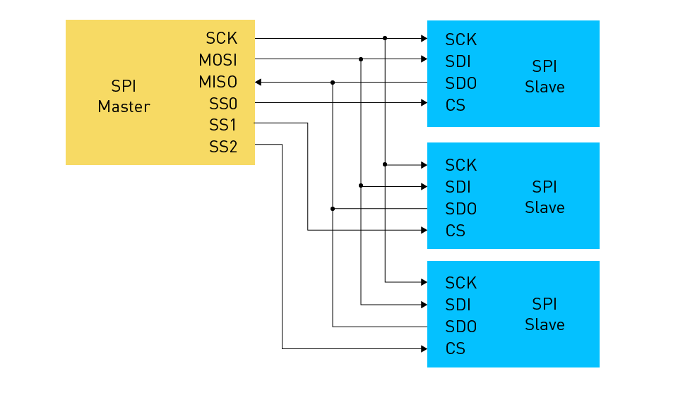
SPI (Serial Peripheral Interface): This master-slave protocol uses three lines typically: MISO (Master In Slave Out), MOSI (Master Out Slave In), and SCLK (Serial Clock), as well as a chip select line for each slave device. Data can be transferred in both ways concurrently since it is full-duplex.

Figure 3: 4-wire SPI bus configuration with multiple slaves
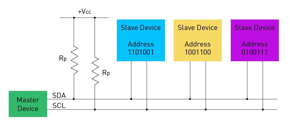
I2C (Inter-Integrated Circuit): It is a multi-master, multi-slave protocol via two wires: SDA for serial data and SCL for serial clock. The I2C bus addresses the devices with a unique address, enabling several devices to share the same communication channels.

Figure 4: I2C bus
Timing Considerations
Timing is crucial for the efficient operation of serial communication. Since the clock signal controls time in synchronous communication, the clock frequency must be appropriate for the ADC and the receiving device. Asynchronous communication requires that the baud rate and data format (start bits, stop bits and parity) match between the devices.
Furthermore, the serial interface's transmission rate is crucial since data is delivered bit by bit. The serial interface must be capable of handling the necessary data rate for high-speed applications.
Advantages and Disadvantages
- Advantages include the following:
- Reduced Pin Count: Needs fewer pins than parallel interfaces, making board design easier and requiring less power and money.
- Longer Communication Distances: They are typically more noise-resistant and able to transmit higher-quality signals across greater distances.
- Flexibility: Several serial protocols enable simultaneous connections of multiple devices to the same bus.
Disadvantages include the following:
- Higher Latency: Since data is transmitted in sequential order, there may be latency during transmission, especially when using big data words or at slower clock speeds.
- Increased Protocol Complexity: Serial protocols, particularly in software, might be more difficult to implement.
Applications where lower pins are needed, greater communication ranges, or more devices connected to the same bus benefit from serial interfaces. The particular needs of the application will eventually determine whether to use a serial or parallel interface.
Differential and Low Voltage Differential Signaling (LVDS) Interfaces
Differential signaling is a technique used to transmit information electrically by utilizing two complementary signals transmitted on separate wires. This contrasts with single-ended signaling, in which the data is transmitted via a single wire and is referenced to a constant voltage (often ground). A well-liked differential signaling standard is LVDS or low-voltage differential signaling.
Basic Operation
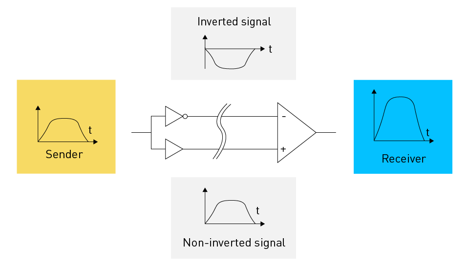
Information is sent through a pair of wires in differential signaling. The inverse of each other's voltage signals is carried by these two lines. The voltage on one wire lowers by the same amount when the voltage on the other wire rises, and vice versa.

Figure 5: Differential signaling
The interface’s receiving end calculates the voltage differential between the two signals rather than their absolute levels. This is useful because common-mode noise equally impacts both cables and has no effect on the signal difference. It is advantageous to use this technology in areas where there is high electromagnetic interference (EMI) because it can efficiently reject noise and interference.
Very low voltages, usually in the region of a few hundred millivolts, are required for LVDS to operate. As a result, LVDS can operate at high data speeds while using relatively little power. Applications that require high-speed data transfer in a noisy environment frequently use the standard.
Applications
High-Speed Data Communication: Due to its low power consumption and strong noise tolerance, differential signaling, most especially LVDS is frequently utilized for high-speed data transfer within and between electronic devices.
ADCs in Noisy Environments: LVDS interfaces are used to preserve the integrity of the digital output from the ADC when it is utilized in electrically loud situations or across long distances.
Video Transmission: LVDS finds extensive usage in the transfer of video data from graphics processing units to display panels, especially in the context of large flat-panel displays and high-definition televisions. The significance of LVDS lies in its ability to ensure high-speed data transmission, which is crucial for maintaining the quality of the displayed images.
Networking Equipment: Differential signaling is widely employed in network routers and switches because it is essential to ensure signal integrity over twisted-pair connections.
Industrial Control Systems: In industrial settings where electromagnetic interference (EMI) levels can be significant, the utilization of differential signaling, such as LVDS is common for ensuring reliable data transmission between sensors, actuators, and control units. This approach helps mitigate the impact of EMI and maintains the integrity of data in industrial control systems.
Selecting the Appropriate Interface
The system output interface is crucial when selecting an ADC's output interface. This decision should be based on a number of variables, such as the particular application needs and system design limitations. Choosing wisely aids in maximizing performance, dependability, and affordability, reliability, and cost.
Application Requirements
Data Rate and Throughput: When dealing with high-speed applications such as digital signal processing or high-definition video, parallel interfaces are often preferred due to their ability to handle high data rates effectively. On the other hand, for low-speed applications like sensor data logging, serial interfaces are more suitable.
Transmission Distance: In scenarios where data needs to be transmitted over long distances, the noise immunity offered by differential interfaces like LVDS makes them a preferred choice. Serial interfaces can also be viable options for moderately long distances, whereas parallel interfaces are generally limited to short distances.
Noisy Environments: In electrically noisy environments, where noise immunity is crucial, the implementation of differential signaling, such as LVDS, is highly effective. For less noisy environments, either serial or parallel interfaces can be utilized.
Power Consumption: Applications that prioritize power efficiency can benefit from utilizing serial interfaces like I2C, as they tend to consume less power compared to parallel interfaces.
Synchronization and Timing: For applications that demand precise synchronization and timing, parallel interfaces are often preferred due to their superior synchronization capabilities.
System Design Constraints
Board Space and Complexity: Multiple data lines are needed for parallel connections, which can increase board complexity and space requirements. Serial interfaces are more compact and simpler to route on a PCB since they have fewer data lines.
Cost: Compared to serial interfaces, parallel interfaces often require more components and cost more money. A serial interface could be a more affordable option if price is a key consideration.
Compatibility with Other Components: It is crucial to confirm that the selected ADC interface is appropriate for use with the system's CPUs, microcontrollers, and other components. This frequently has a big impact on the interface choice.
Scalability and Future Proofing: The system's ease of scaling and upgrading should be taken into account. In order to accommodate more devices on one bus, a serial interface like I2C may be more scalable
Development and Debugging Tools: Especially for complex systems, the availability of development tools and the simplicity of debugging are crucial factors to take into account.
In conclusion, choosing the best ADC output interface requires carefully examining the needs of the application and the limitations of the system's design. A system that achieves the desired performance and cost criteria will be more reliable and effective as a result of balancing these elements.


直接登录
创建新帐号