Principles of Electromagnetic Induction
The principles of electromagnetic induction, discovered in the early 19th century and considered a fundamental idea in the field of electromagnetism, underpin the operation of transformers. Understanding electromagnetic induction is necessary in order to comprehend how transformers are able to change the level of an alternating current voltage from one to another without establishing a direct electrical connection between the circuits. This section explores the fundamentals of electromagnetic induction as well as its application in transformer operation.
Electromagnetic Induction: The Basic Principle
Induction of electromagnetic fields occurs when a fluctuating magnetic field within a coil of wire produces an electromotive force (EMF) or voltage across the coil. This phenomenon is referred to as electromagnetic induction. Michael Faraday was the first person to describe this phenomenon. He discovered that a constantly changing magnetic field induces a voltage in a conductor. According to Faraday's Law of Electromagnetic Induction, the induced electromagnetic field (EMF) in any closed circuit is equal to the rate at which the magnetic flux changes through the circuit.
Two key processes underpin electromagnetic induction:
Mutual Induction: Mutual induction occurs when a fluctuating magnetic field in one coil induces an electromagnetic field (EMF) in a nearby coil. According to this concept, transformers operate by creating a fluctuating magnetic field through the alternating current flowing through the primary coil, which in turn induces an electromagnetic field (EMF) in the secondary coil.
Self-Induction: Self-induction is the process where a changing current within a coil induces an electromagnetic field (EMF) in the same coil due to the coil's own changing magnetic field. Despite the essential role of self-induction in inductance, mutual induction primarily governs the operation of transformers.
Application in Transformers
A transformer's primary winding produces a magnetic field as alternating current (AC) flows through it. The intensity of this magnetic field varies with the current frequency. The transformer's ferromagnetic core directs this magnetic field, ensuring its passage through the secondary winding. The fluctuating magnetic field induces an electromagnetic field (EMF) in the secondary winding through a process known as mutual induction. The turns ratio, defined as the ratio of the primary winding's turns to the secondary winding's, determines the magnitude of the induced voltage in the secondary winding relative to the primary winding's voltage.
$$\text{Turns Ratio} = \frac{N_1}{N_2}$$The rate at which flux connections change determines the amount of induced electromagnetic field (EMF) in a coil. According to Faraday's second law of electromagnetic induction, the induced electromagnetic field (emf) in a coil is exactly proportional to the rate of change of flux connections.
$$e = -N \frac{d\phi}{dt}$$In this equation, e represents the induced EM in volts, N represents the number of turns, and
$$\frac{d\phi}{dt}$$represents the rate of change of the flux. Given the identical flux change rate for both windings, the number of turns in each winding determines the size of the induced EMF in both the primary and secondary windings.
The transformation ratio of the transformer, denoted by the letter K, specifies the proportion of the secondary voltage to the primary voltage being applied.
$$K = \frac{N_2}{N_1}$$Key Factors Influencing Induction in Transformers
Magnetic Core Material: The core material's magnetic permeability has a significant impact on the effectiveness of magnetic flux linkage between the primary and secondary windings. This efficiency is also referred to as the magnetic flux linkage efficiency. When it comes to the construction of transformer cores, high-permeability materials like silicon steel are frequently utilized. The aim is to minimize energy losses and maximize induction efficiency.
Frequency of the AC Supply: The frequency of the AC current flowing through the primary winding determines the rate of change of the magnetic field and, consequently, the amount of electromagnetic field (EMF) induced in the secondary winding. Power distribution systems design transformers to operate at specific frequencies, typically between 50 and 60 Hz, to maximize efficiency.
Physical Arrangement of Windings: Another factor that can affect the efficiency of electromagnetic induction is the degree of connection between the main and secondary windings. This factor is referred to as the physical arrangement of the windings. A close physical and magnetic coupling guarantees that the majority of the magnetic flux generated by the primary winding links with the secondary winding. This helps to minimize leakage flux and maximize the efficiency of the transformer.
Transformer Construction and Components
Transformers are complex devices that use electromagnetic induction principles to transfer energy between circuits at different voltage levels. Transformers are used to transmit energy. The structure of these devices is crucial to their utility, as it not only dictates their efficiency and effectiveness, but also the variety of applications they can serve. This section provides an in-depth analysis of the fundamental elements that comprise a transformer, including the core, windings, insulation, and the concepts of transformer turn ratio and voltage control, both of which are particularly important for comprehending a transformer's operation.
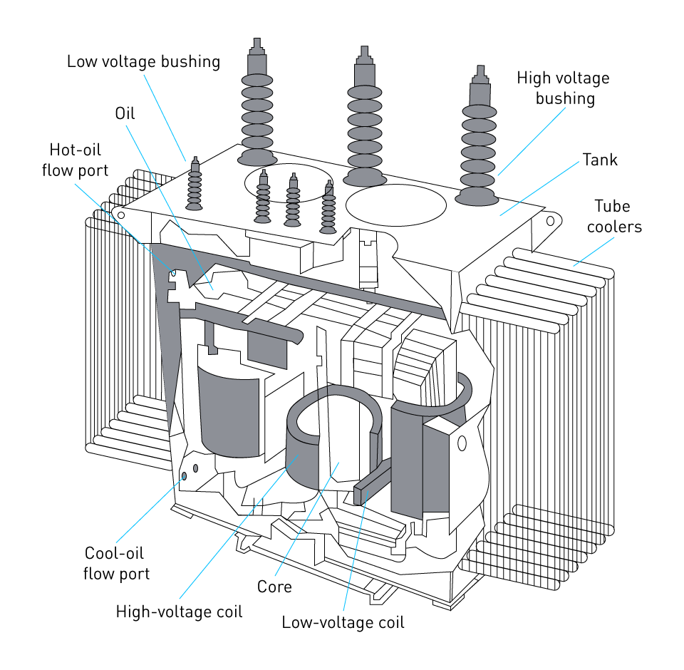
Figure 3: High-power transformer cutaway view
Core
The core of the transformer acts as the pathway for the magnetic flux that the primary winding of a transformer produces and directs to the secondary winding. Furthermore, it is frequently constructed from materials with high permeability, such as silicon steel, in order to reduce the amount of energy lost and ensure that the magnetic flux is transported effectively between the windings. Examples of common core configurations include the core-type configuration, where the windings encircle the core material, and the shell-type configuration, where the core encircles the windings. A number of parameters, such as the desired voltage level, transformer size, and efficiency standards, influence the decision between these designs.
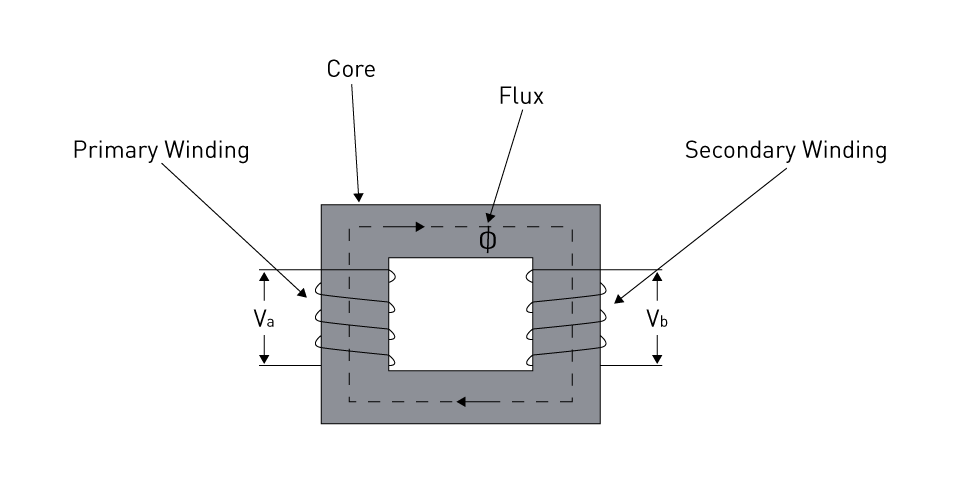
Figure 4: Core type transformer
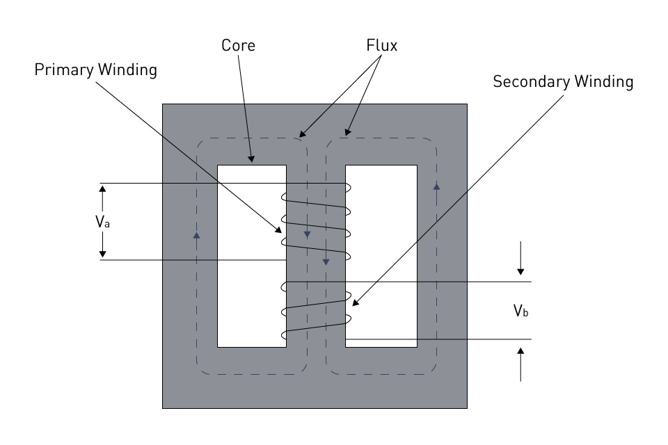
Figure 5: Shell type transformer
Applications with high voltage and high power, such as power generating and transmission substations, as well as those with inductive loads, typically use transformers of the core type.
Transformers of the shell type are appropriate for applications requiring low to medium voltage, such as distribution transformers and special-purpose transformers, as well as situations that require high efficiency and a compact design.
Windings
Windings are the conductive coils that transport the primary and secondary currents in a transformer. Windings are also known as windings. Both the primary winding and the secondary winding are linked to the load. The primary winding is connected to the power source. Copper or aluminum wire is used to construct the windings, and they are meticulously insulated from one another as well as the core in order to avoid any electrical shorts from occurring. The capability of the transformer to transform voltage is determined by the number of turns in both the primary and secondary windings, as well as the magnetic characteristics of the core.
Concentric and sandwiched windings are the two primary types of windings that are used in transformers. Core-type transformers utilize concentric windings. Almost all shell-type transformers make use of sandwiched windings in their operational configuration.
Insulation
When it comes to preventing electrical and thermal failures in transformers, insulation is absolutely necessary. The primary and secondary windings are separated from one another as well as from the core of the transformer by this component, which prevents any electrical energy from escaping between the various components. Paper, polymer, and oil are some of the insulation materials that are utilized. Each of these materials is chosen for its dielectric strength, thermal stability, and compliance with the operating conditions of the transformer. To be able to endure the electrical stresses and temperatures that are encountered during operation, the insulating system needs to be properly constructed through careful planning.
There are two primary categories that can be used to categorize transformer insulation: main insulation and mirror insulation.
Major Insulation: Important insulation for high-voltage components, such as insulation between windings, core, and ground; the term "major insulation" refers to this type of insulation. Materials such as pressboard, Kraft paper, epoxy resin, and insulating oil are utilized in its construction.
Minor Insulation: Minor insulation refers to insulation for lesser voltage variations inside windings, typically consisting of turn and layer insulation. Materials such as varnish, enamel, and thin insulating sheets or films are utilized in its production.
Bushings
Insulating devices known as bushings make it possible for electrical conductors to travel through the grounded transformer tank without risk of interruption. In addition to providing electrical insulation and mechanical support for the high-voltage leads, they also make it easier to connect the internal windings to the external power circuits. Ceramic, epoxy resin, or composite polymers are some of the materials that are used in the production of bushings. These materials are engineered to endure high levels of electrical and mechanical stress.
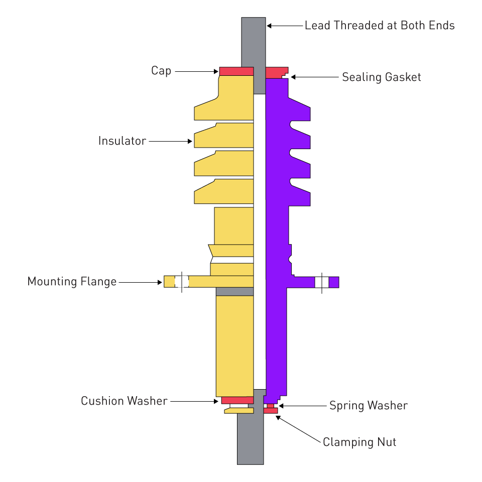
Figure 6: Transformer bushing
Bushings fall into the following categories based on their design and the uses they serve:
Oil-filled Bushings: Bushings that are filled with oil are a type of bushing that is frequently utilized in high-voltage transformers. These bushings are filled with insulating oil. In addition to providing superior insulating and cooling capabilities, the oil also contributes to the bushing's enhanced performance and increased longevity.
Solid-type Bushings: These bushings are utilized in applications that require lower voltage and are constructed from solid insulating materials such as epoxy or porcelain by their manufacturers. In addition to providing dependable insulation, they do not require the use of oil or gas filling.
Capacitive-graded Bushings: These bushings have a graded insulating structure that minimizes the electric field stress along the bushing. As a result, the bushing's performance and reliability in high-voltage applications are improved.
Transformer Tank
The transformer tank is an essential component of a transformer because it houses the core as well as the windings. It provides both structural support and protection from adverse environmental conditions. In most cases, the tank is constructed out of steel, and it is intended to be able to withstand the internal pressures that are brought about by the thermal expansion and contraction of the protecting oil.
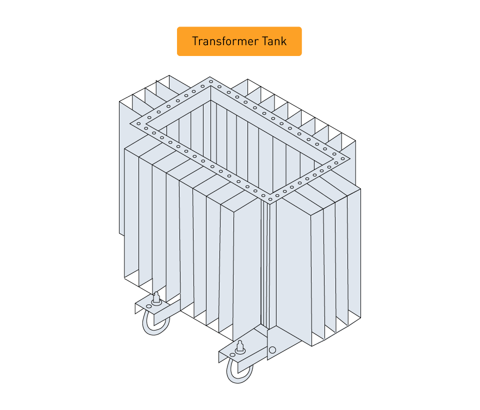
Figure 7: Transformer tank
Among the most important characteristics of the transformer tank are the following:
Cooling System: The tank is fitted with radiators, fins, or fans as part of its cooling system in order to dissipate the heat that is produced while it is in operation. It is essential to ensure that the transformer is properly cooled in order to preserve its efficiency and extended lifespan.
Oil Preservation System: A conservator or a nitrogen blanket are examples of oil preservation systems that are included in the tank of oil-filled transformers. These systems are designed to preserve the quality and quantity of the insulating oil so that it can continue to function properly.
Pressure Relief Devices: The tank is protected from overpressure circumstances that are brought either by internal flaws or external impacts by these mechanisms, which are known as pressure relief devices. In order to prevent the tank from rupturing and to guarantee safe operation, they expel any excess pressure.
Gaskets and Seals: The tank is sealed with gaskets and seals to prevent the intrusion of moisture and pollutants, which could damage the insulating oil and have a negative impact on the operation of the transformer.
When performing routine maintenance on the transformer tank, it is necessary to check for leaks, make certain that the gaskets and seals are intact, and keep an eye on how well the cooling system is functioning. When it comes to the overall dependability and effectiveness of the transformer, appropriate maintenance of the transformer tank is absolutely necessary.


直接登录
创建新帐号