Mathematical Foundation
A mathematical framework capable of accurately representing the cyclical character of voltage and current waveforms is essential for the analysis of alternating current (AC) power systems. In order to achieve this, phasors and complex numbers are essential tools that offer a sophisticated yet understandable way to describe the behavior of AC circuits. The mathematical basis for analyzing real, reactive, and apparent power in AC systems is presented in this section, with an emphasis on the function of phasors and complex numbers.
Phasors
A phasor is a complex number that describes the amplitude and phase angle of a sinusoidal function, like voltage or current in an alternating current circuit. The term "phasor" is derived from "phase vector," emphasizing its capacity to represent both amplitude (magnitude) and phase information in a single mathematical object. Phasors simplify the study of alternating current circuits by transforming differential equations of sinusoidal functions into algebraic equations, allowing linear algebra methods to be applied to circuit problems.
A phasor can be expressed mathematically as:
$$\text{Phasor} = A \angle \theta$$where θ is the phase angle, expressed in degrees or radians, and Α is the waveform's magnitude (or amplitude). This representation is equal to the complex number Α\( e^{j \theta} \), where j is the imaginary unit (j2=−1) and \( e^{j \theta} \) is the unit circle in the complex plane.
Complex Numbers in AC Power Analysis
In AC power analysis, complex numbers are employed to represent both voltage and current phasors, as well as circuit element impedances. A circuit element's impedance, which can be resistive, inductive, or capacitive, is represented as a complex number that includes both the resistance (real part) and reactance (imaginary part) of the element.
Real power (P), reactive power (Q), and apparent power (S) are the three complex terminology used to describe power in an AC circuit. The definition of the complex power S is:
$$S = P + jQ$$where:
The real power, P (measured in watts, W), represents the average power consumed by the circuit for a whole cycle. It is the power that works or generates heat.
The reactive power, Q (measured in volt-amperes reactive or VAR), oscillates between the source and reactive elements in the circuit (inductors and capacitors). It does not generate work but is required for the formation of magnetic and electric fields.
The apparent power S (measured in volt-amperes or VA) is the product of RMS voltage and current. It shows the overall power flow in the circuit, which includes both real and reactive power components.
The apparent power is given by the magnitude of the complex power |S|, and the phase difference between the current and voltage is represented by the angle of S (commonly written as φ), which is important to know in order to calculate the circuit's power factor.
Physical Interpretation
Real, Reactive, and Apparent Power
The concepts of real, reactive, and apparent power are essential for understanding how energy flows in alternating current power systems. Each form of power has a distinct purpose, influencing everything from electrical system design and operation to energy efficiency measurement and improvement. This section delves into the physical interpretation of different power categories and their relevance in real-world applications.
Real Power (P)
Real power, measured in watts (W), denotes the real work performed by an electrical system. It is the power required by resistive loads to accomplish useful tasks such as lighting, heating, and motor operation. Real power is the component of power that converts energy into forms capable of doing work, such as heat, light, and motion. It measures the electrical system's ability to conduct productive operations that need energy conversion from one form to another.
In a domestic setting, actual power powers household appliances and devices, which directly correlates to the energy consumption reported by utility companies. In an industrial context, it powers machinery and equipment, emphasizing the significance of effective real power utilization in operational cost management.
Reactive Power (Q)
Reactive power, measured in volt-amperes reactive (VAR), is the power that alternates between the circuit's source and reactive components, such as inductors and capacitors. This form of power does not contribute to any work; rather, it is required to establish the electric and magnetic fields needed for the operation of various electrical devices.
Reactive power is necessary for the operation of AC systems but does not directly result in energy consumption. It impacts voltage levels across the electrical system, which can lead to inefficiencies and increased losses if not regulated effectively. Excessive reactive power can create voltage drops and may demand larger conductors and equipment to manage higher currents, resulting in higher system costs.
Apparent Power (S)
Apparent power, measured in volt-amperes (VA), is the sum of real and reactive power. It represents the overall power flow in the circuit and is the product of the circuit's voltage and current, ignoring the phase angle. Electrical systems must be constructed to manage apparent power, which determines the size and rating of electrical infrastructure such as generators, transformers, and transmission lines.
The concept of apparent power is critical for effectively designing and operating electrical systems. It aids in determining the capacity of electrical equipment to guarantee that it can manage both productive and non-productive components of electrical power. Furthermore, the link between actual, reactive, and apparent power is important in calculating a system's power factor, which is a measure of how efficiently electrical power is turned into usable work output.
Visualization Techniques
Phasor diagrams are an effective tool for visualizing and comprehending the interactions of real, reactive, and apparent power in AC circuits. Phasor diagrams make it easier to analyze and grasp complex power ideas because they show the magnitude and phase correlations of electrical quantities as vectors in a two-dimensional plane. This section investigates how phasor diagrams are used to represent these power categories and explain how they interact inside AC power systems.
Phasor Diagram Basics
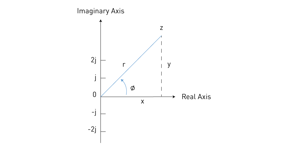
A phasor is a vector that describes the magnitude and phase angle of a sinusoidal function with respect to a reference. In the context of AC power analysis, voltage, current, and complex power can all be represented by phasors. The horizontal axis usually represents the real component (in-phase component), and the vertical axis represents the imaginary component (quadrature component).

Figure 7: Representation of complex number z = x + jy = r\( \angle \phi \)
Visualizing Real, Reactive, and Apparent Power
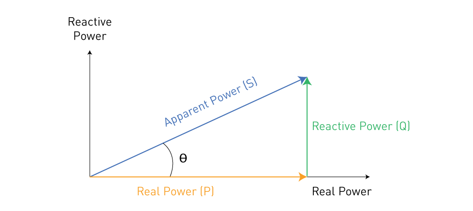
Real Power (P): Real power is represented on the horizontal axis of the phasor diagram. It relates to the component of power that does actual work, as indicated by the apparent power vector projected onto the real axis. The length of this projection represents the amount of real power in the circuit.
Reactive Power (Q): Reactive power is represented on the vertical axis. It shows the power oscillating between the circuit's source and reactive parts, such as capacitors and inductors. The apparent power vector is projected onto the reactive axis, indicating the magnitude of reactive power.
Apparent Power (S): The vector formed by the addition of the real and reactive power components is used to represent apparent power. The magnitude of this vector represents the total power flowing through the circuit, while its angle with respect to the real axis (the power factor angle) offers information about the circuit's efficiency.
The power triangle, seen in the figure below, can be used to graphically represent complex power. The horizontal axis represents real power, the vertical axis represents reactive power, and the vector combination of real and reactive power produces apparent power.

Figure 8: Power triangle
Interpreting Phasor Diagrams
Phasor diagrams allow engineers to visually examine the phase connection between voltage and current in an AC system, which has a direct impact on the distribution of both real and reactive power. Examining the length and direction of the phasor representing apparent power allows one to easily establish the system's power factor, evaluate whether actual or reactive power predominates, and measure overall power efficiency.
In addition, phasor diagrams play a crucial role in power system design and analysis, particularly when it comes to activities like power factor correction, filter circuit design, and optimizing power delivery to lower losses and boost stability.


直接登录
创建新帐号