Resistive, Inductive, and Capacitive Loads
Characteristics and Behavior in AC Circuits
Understanding the fundamental properties and behaviors of resistive, inductive, and capacitive loads in alternating current circuits is critical for successful electrical engineering and circuit design. These three types of loads behave differently when exposed to alternating current (AC), which has a direct impact on AC circuit analysis, design, and performance.
Resistive Loads: Ohm's law (V = IR) states that there is a straight relationship between voltage and current for resistive loads, such as heaters and incandescent light bulbs. The waveforms of an AC circuit rise and fall simultaneously without phase shifting because the current flowing through a resistor is in phase with the voltage across it. Real power (P), which is computed as the power used by a resistive load, is
$$P = V \cdot I \cdot \cos(\phi)$$where φ represents the phase angle of current and voltage. For purely resistive loads, φ = 0, resulting in a power factor of 1, showing optimum efficiency without reactive power.
Inductive Loads: Motors, transformers, and coils are examples of inductive loads that store energy in a magnetic field when current runs through them. Inductive loads in AC circuits cause the current to lag behind the voltage by 90° (φ = -90°). This phase shift happens when the inductor opposes changes in current flow, causing a delay in the current waveform relative to the voltage waveform. The power associated with inductive loads is primarily reactive power (Q), which does not produce work but oscillates between source and load. This results in a power factor less than one, indicating the presence of reactive power and lower efficiency.
Capacitive Loads: Capacitive loads, such as capacitors, store energy in an electric field and behave in the opposite way as inductive loads in alternating current circuits. In a capacitive load, current leads voltage by 90 degrees (φ = 90°). This phase shift occurs because of the capacitor's ability to store and release charge, causing the current to grow before the voltage reaches its peak. Capacitive loads, like inductive loads, largely contribute to reactive power (Q) in the circuit; however, the reactive power flows in the opposite way. The presence of capacitive loads can increase a circuit's power factor by countering the effects of inductive loads, reducing overall reactive power while enhancing efficiency.
Behavior in AC Circuits: To ensure the desired performance, efficiency, and stability, engineers must take into account the distinct phase relationships and power characteristics of resistive, inductive, and capacitive loads when designing AC circuits. For instance, the selection and layout of components in power distribution systems, electronic devices, and signal processing circuits are impacted by the requirement to regulate the phase shifts and power factors generated by these different loads.
RLC Circuits
RLC circuits, which are made up of resistors (R), inductors (L), and capacitors (C), are important in the field of AC circuit analysis. These circuits provide different behaviors and challenges depending on whether they are arranged in series or parallel. Understanding resonance and the quality factor (Q-factor), which are essential to the design and optimization of electronic circuits for a variety of applications, is a vital component of their study.
Series RLC Circuits
A series RLC circuit consists of a resistor, inductor, and capacitor all connected in series.
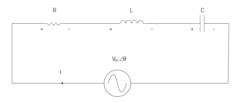
Figure 9: Series RLC circuit example
The circuit's total impedance (Z) is a complicated number that includes the resistive (R), inductive (XL = ωL), and capacitive (XC = 1/ωC) reactances, where ω represents the angular frequency of the AC supply. The impedance formula for a series RLC circuit is:
$$Z = R + j(X_L - X_C)$$It shows that the inductive and capacitive reactances subtract since their effects are opposite.
In a series RLC circuit, resonance occurs when the inductive and capacitive reactances have the same magnitude but opposite phase, leading them to cancel out. At this time, the circuit's impedance is solely resistive, and its overall impedance is at its lowest, resulting in maximum current flow.
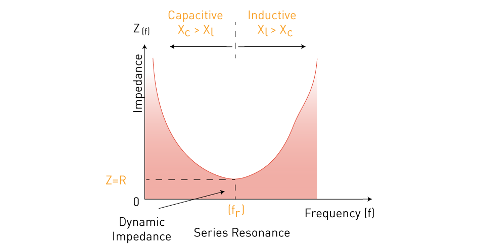
Figure 10: Impedance in a series RLC circuit as a function of frequency
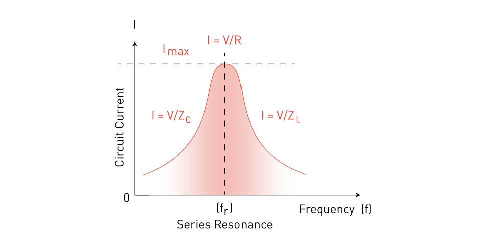
Figure 11: Series RLC circuit current as a function of frequency
The resonant frequency (f0) can be measured with
$$ f_0 = \frac{1}{2\pi\sqrt{LC}} $$The frequency of resonance (f0) is indicated here.
Parallel RLC Circuits
Parallel RLC circuits have a resistor, inductor, and capacitor linked in parallel, resulting in numerous routes for current flow.
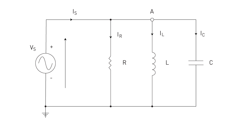
Figure 12: Parallel RLC circuit
The circuit's impedance is given by the following equation.
$$ Z_{\text{Total}} = \frac{1}{\left(\frac{1}{Z_R} + \frac{1}{Z_L} + \frac{1}{Z_C}\right)} $$The resonance condition in parallel circuits is similar to that in series circuits; it occurs when the net reactance is zero, enhancing the circuit's resistance while limiting current flow. The resonant frequency is found using the same formula as in series circuits.
Q-factor
The quality factor, or Q-factor, of an RLC circuit is a dimensionless parameter that measures the sharpness of resonance. It is defined as the resonant frequency divided by the bandwidth of the resonant peak, where the bandwidth is the difference between frequencies at which the power is half of its peak value.
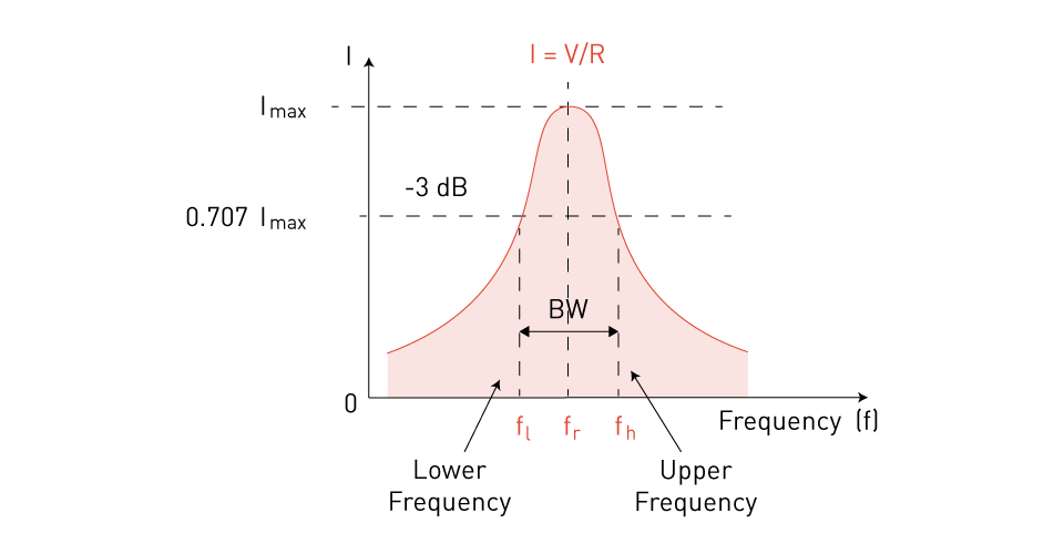
Figure 13: Series resonance circuit bandwidth
In series RLC circuits, the Q-factor is given by
$$ Q = \frac{1}{R} \sqrt{\frac{L}{C}} $$And in parallel RLC circuits, it is given by.
$$ Q = R \sqrt{\frac{C}{L}} $$A higher Q-factor suggests a smaller bandwidth and a greater peak at resonance, implying reduced losses and a more selective circuit capable of successfully filtering out a specific range of frequencies.
Applications and Implications
The study of series and parallel RLC circuits, including their resonance behavior and Q-factor, is critical for designing filters, oscillators, and other signal processing devices. Understanding these concepts enables engineers to design circuits at certain frequencies, maximize energy transfer, and accomplish desired results in analog and digital electronics. Mastery of RLC circuit analysis, including steady-state and transient analysis, is required for the successful design and optimization of a wide range of electronic systems and devices.
Steady-state Analysis
Engineers employ a number of approaches to calculate voltages and currents across various components within an alternating current circuit, particularly when operating under steady state circumstances. After all transient reactions have dissipated, the circuit activity settles into a consistent pattern, which is referred to as steady-state analysis. This section covers the main methods and tools for steady-state analysis of AC circuits, including nodal analysis, mesh analysis, the superposition theorem, source transformation, Thevenin and Norton equivalents, and computer-based tools.
Nodal Analysis
In AC circuits, nodal analysis involves applying Kirchhoff's Current Law (KCL) to the nodes to determine their potentials in relation to a reference node. This approach employs the notion of node voltages as variables to ease the process of solving circuits with many nodes. Nodal analysis in alternating current circuits uses complex numbers to account for phase changes between voltage and current. Impedances are employed instead of resistances, and the equations are written in the phasor domain to solve for the unknown node voltages.
Mesh Analysis
Mesh analysis uses Kirchhoff's Voltage Law (KVL) to analyze loops or meshes in a circuit. Mesh analysis in AC circuits, like nodal analysis, takes into account impedances and phasor representations of voltage and current. The goal is to create loop current equations for independent loops and solve them concurrently to determine the phasor values associated with currents flowing around these loops, which would substantially simplify the analysis of circuits that have multiple meshes.
Superposition Theorem
According to the superposition theorem, in a linear circuit with multiple independent sources (voltage or current), the response (voltage or current) in any branch is the algebraic sum of the responses caused by each independent source acting alone, while all other independent sources are represented by their internal impedances. This theorem is especially useful in AC circuits for determining the influence of each frequency component or source inside the circuit.
Source Transformation
Source transformation is a technique for simplifying circuit analysis that converts a voltage source in series with an impedance to an equivalent current source in parallel with the same impedance, and vice versa. This strategy is useful in situations when specific types of sources are easier to manage or when attempting to reduce the number of sources in the circuit.
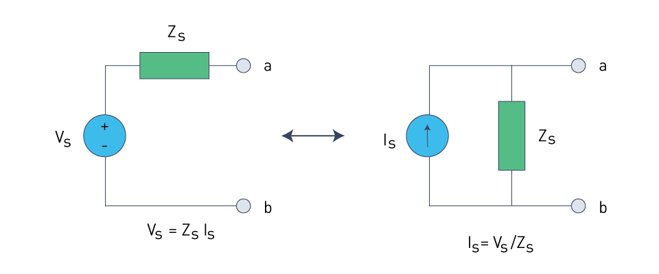
Figure 14: Source transformation
Thevenin and Norton Equivalent Circuits
Thevenin's theorem states that a linear two-terminal circuit may be substituted by an equivalent circuit made up of a voltage source (Thevenin voltage) in series with an impedance. Norton's theorem, on the other hand, visualizes the circuit as a current source (Norton current) in parallel with an impedance. These theorems are often used in AC circuit analysis to help with the study of power systems and other complicated circuits.
Computer-based Tools for AC Circuit Analysis
With the complexity of today's electrical systems, computer-based tools like SPICE, MATLAB, and other circuit modeling software have become vital. These tools enable extensive modeling of AC circuit behavior, including transient and steady-state analysis, by numerically solving circuit equations. They allow you to model complicated circuits with several components and sources, perform frequency response analysis, and anticipate circuit behavior under a variety of operational situations without using physical prototypes.
Transient Analysis in AC Circuits
Transient analysis in AC circuits, particularly in RLC circuits, is an important topic of research in electrical engineering. This study focuses on how circuits behave when they are subjected to sudden changes in supply voltage or current, such as when a circuit is turned on for the first time, when switches are opened or closed, or when the load changes abruptly. These transitory situations cause inductors and capacitors to temporarily store and release energy, resulting in oscillatory or exponential responses that gradually settle into a steady state.
Fundamental Concepts
The transient response of an RLC circuit is determined by the intrinsic properties of its inductive (L), capacitive (C), and resistive (R) components. Inductors and capacitors store energy as magnetic fields and electric fields, respectively. When the state of the circuit changes, these fields either increase or decrease, influencing the current and voltage across the circuit components.
- Inductors resist current changes, resulting in a slow adjustment of current flow.
- Capacitors withstand voltage fluctuations, causing the voltage across them to gradually adjust over time.
Mathematical Analysis
The investigation of transient responses in RLC circuits usually entails solving differential equations that characterize the circuit's behavior. These equations are based on Kirchhoff's voltage and current laws, as well as the constitutive relations of capacitors and inductors. The solution to these differential equations explains how voltages and currents change over time from an initial condition to a steady state.
Types of Transient Responses
Overdamped Response: When the circuit's resistance is large in comparison to its inductance and capacitance, an exponential decay occurs, resulting in a steady state free of oscillation.
Critically Damped Response: Represents the scenario with the lowest resistance that still helps prevent oscillation, allowing the system to attain its steady state as soon as possible without overshoot.
Underdamped Response: Characterized by lowered resistance, which causes oscillatory behavior in which the system oscillates around the steady-state value with exponentially decreasing amplitude.
Undamped Response: No resistance in an idealized case causes a constant oscillation at the circuit's natural resonant frequency.
Role of Natural Frequency and Damping Ratio
The transient response may be characterized by two important parameters: the damping ratio (ζ) and the natural frequency (ω0). The natural frequency ( ω0 =\( \frac{1}{\sqrt{LC}} \) ) represents the oscillation rate of the circuit in the absence of damping. It is obtained from the inductance and capacitance. The transient response's type (overdamped, severely damped, or underdamped) is determined by the damping ratio, which is a function of capacitance, resistance, and inductance.
Real-world Implications
Transient analysis is critical for the design and operation of electrical and electronic systems, ensuring that components can withstand unexpected changes without causing damage or unwanted behavior. It guides the selection of components in power systems, signal processing, and power quality management. Understanding transient behavior allows engineers to design circuits that respond appropriately to switching events, power surges, and other transient phenomena, hence improving the reliability and performance of electrical systems.


直接登录
创建新帐号