AC Power Definition
Modern electrical systems are built on alternating current (AC) power, which powers homes, companies, and infrastructure worldwide. AC electricity oscillates back and forth in contrast to its counterpart, Direct Current (DC), which flows in a consistent direction.
The resistance and current in a circuit determine its power loss, not the circuit's AC or DC voltage. Since the resistance is constant, less current must be used in order to minimize losses. Transformers step up (boost) the voltage for AC power transmission and step down (lower) it for local distribution. Transmission losses are decreased by stepping up the voltage since it lowers current. This essential property makes it possible for AC power to be effectively transferred over great distances, a quality that has influenced the growth and distribution of electricity around the world.
AC Power Definition: The type of electric power that is supplied to homes and businesses in which the direction of the electric charge flow alternates on a regular basis is known as AC power. This reversal occurs at a consistent frequency, typically 50 or 60 times per second (Hertz), across the majority of nations. The crucial function that AC power plays in the electrical grid is highlighted by its ability to efficiently distribute over large networks and convert between high and low voltages with ease through the use of transformers.
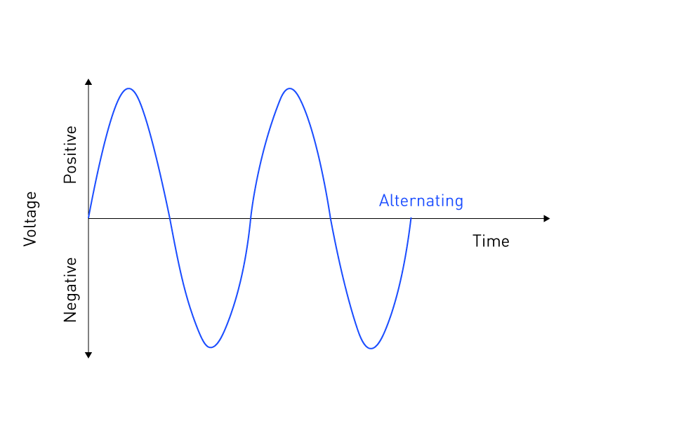
Figure 1: AC power waveform
The "War of Currents" in the late 19th century, which resulted in a triumph for AC mainly because of AC's advantage in long-distance electrical transmission, was the reason why AC power was adopted over DC rather than DC.
These days, the use of AC electricity goes beyond simple heating and lighting to include sophisticated technological equipment, transportation networks, and industrial machines. Modern electrical engineering and energy distribution networks continue to rely heavily on AC power due to its versatility, efficiency, and safety in both residential and commercial settings.
AC vs. DC Power
To understand the essence of modern electrical engineering, one must first understand the differences between Alternating Current (AC) and Direct Current (DC). This difference clarifies the distinct qualities and uses of every kind of current while also providing insight into the evolution of electrical power networks across time.
Historical Rivalry
The "War of Currents," which pitted AC against DC power, was a pivotal moment in late 19th-century physics. In the vanguard of this conflict were Nikola Tesla and George Westinghouse, who supported AC power, on the other side, there was Thomas Edison, who supported DC electricity. DC served as the foundation for Edison's early electrical system research and implementation. But Tesla's AC systems had a lot going for them, especially when it came to long-distance power transmission, which made AC the standard method of distributing electricity in the end. This historical conflict had enormous impact on the economy and was more than just a technical disagreement; it was also a quest for dominance over the developing electrical field.
Technical Differences
The direction of the electron flow is the main technical distinction between AC and DC power. Electrons in DC systems only move in one direction, which maintains a steady voltage. Because of its constancy, DC is perfect for applications like electronic gadgets that need steady, dependable power. On the other hand, the direction of electron flow periodically changes in AC systems. Because of its alternating nature, power distribution is optimized and losses are minimized through the easy use of transformers to step up or step down voltage levels.

Figure 2: DC vs. AC power
AC Power: Its capacity to alter both direction and voltage level qualifies it for grid-based electrical energy delivery.
DC Power: keeps a steady voltage and it only flows in one direction, which makes it perfect for electronics, various motor types, and battery-operated devices.
Current Relevance
Both AC and DC electricity are important in today's society, and they each have specific uses due to their inherent benefits. The widespread use of AC power in ordinary power distribution systems is due to its easy voltage transformation and effective transmission capabilities. Because AC is easily converted to other voltages and electrical gadgets are made to run on AC input, the majority of houses and businesses are powered by it.
On the other hand, DC power has made a name for itself in a number of contemporary applications, such as data centers, electric cars, and electronic devices. The emergence of solid-state electronics and the requirement for energy storage solutions have strengthened the position of DC power in particular industries, like batteries-powered electric vehicles and portable gadgets (which are fundamentally DC sources).
Further reviving interest in DC transmission and distribution networks are the incorporation of renewable energy sources into the grid and the growing need for high-efficiency, low-emission technology. These networks may provide increased dependability and efficiency, particularly for underwater and long-distance power transmission.
Table 1: AC and DC Power Applications
| AC Power Applications | DC Power Applications |
|---|---|
| Residential lighting | LED lighting |
| Industrial motors | Mobile phones |
| HVAC systems | Battery backup systems |
| Household appliances | Electric vehicles (EVs) |
| Power grid distribution | Drones |
Key Properties of AC Power
Three fundamental properties of Alternating Current (AC) power are amplitude, frequency, and phase. In addition to defining the features of AC power, these attributes also support its adaptability and effectiveness in a variety of applications. It is essential for engineers and technicians who work with AC power systems to comprehend these features.
Amplitude
The amplitude of an alternating current waveform is defined as its peak value, which reflects the maximum strength of the electric field or the highest voltage or current in a cycle. Practically speaking, amplitude is equivalent to the "height" of the waveform in a graphic representation. Higher amplitudes indicate that more power can be applied to a load; this is directly correlated with the system's power capacity. In order to guarantee that every device receives the proper amount of power for its operation, engineers use amplitude control to regulate the power levels supplied to multiple devices.
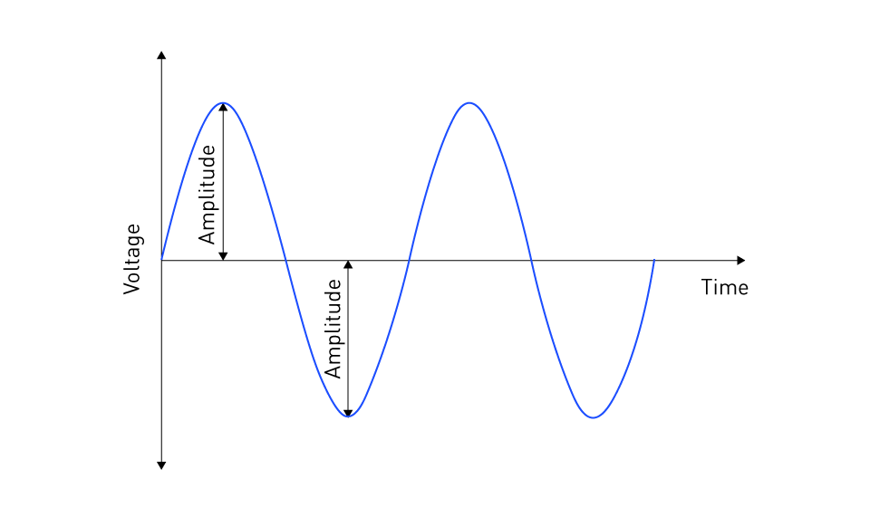
Figure 3: Amplitude
Frequency
The frequency, expressed in Hertz (Hz), tells us how many waveform cycles there are in a second. It is a vital property of AC power that has an impact on everything from the grid's stability to the way electric motors operate. In most of Europe, Asia, Africa, and Australia, the standard frequency is 50 Hz; in North America and some regions of South America, it is 60 Hz. These standard frequencies are frequently intended for device operation; variations may cause harm or ineffective operation. In electricity networks, frequency needs to be carefully controlled to provide grid synchronization, guaranteeing stability and facilitating effective distribution and transmission.

Figure 4: Frequency
Phase
A waveform's phase indicates where it is in relation to other waveforms in time. For effective power transmission and motor functioning in AC power systems, particularly those that use polyphase (e.g., three-phase) systems, the phase difference between the individual waveforms is necessary. The waveforms in a three-phase system are normally 120 degrees out of phase with one another, which results in a more steady power flow and more smoothly and effectively operating electric motors. Designing and running AC power systems requires an understanding of and ability to govern phase relationships, especially in industrial settings where three-phase power is standard procedure.
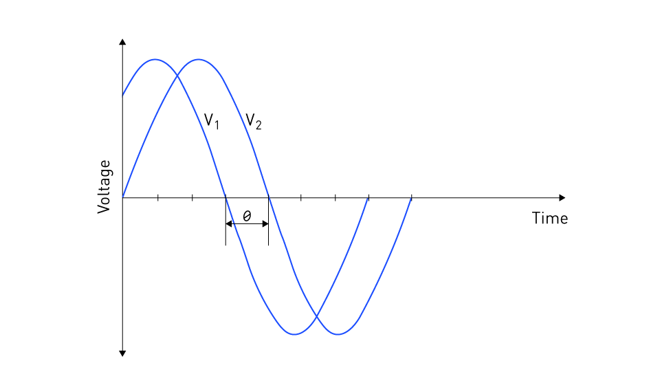
Figure 5: Phase difference between voltages V1 and V2
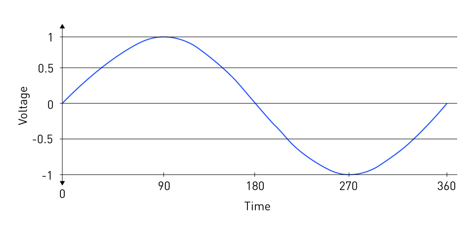
Figure 6: Single phase power
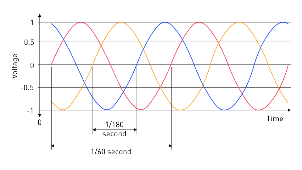
Figure 7: Three phase power
Utilization of AC Power Properties in Various Applications
The three fundamental properties of AC power—amplitude, frequency, and phase—are widely used in a variety of fields:
Electric Power Transmission and Distribution: Long-distance transmission uses high voltages (amplitude) to prevent energy loss, with transformers altering voltage levels for local distribution and end-use.
Motor Operation: AC motors are intended to run at specified frequencies, and three-phase power provides a constant rotating force. Variable frequency drives (VFDs) use the principle of adjusting the frequency to control the speed of the motor.
Renewable Energy Systems: Inverters match the amplitude and frequency of the grid to ensure compatibility while converting DC electricity from solar panels or batteries to AC power.
Electrical Appliances: In order to ensure safe and effective functioning, many home appliances are made to run at the normal AC frequency and voltage of their locality.
Measuring AC Power
For electrical system design, operation, and monitoring, precise AC power measurement is essential. Measurement methods have changed dramatically since the invention of digital technology, offering more precision, adaptability, and insights into power quality and system performance. Digital measuring methods assess the electrical characteristics of AC power by using complex algorithms and processing capability. The concepts and uses of digital measurement techniques in AC power systems are covered in detail in this section.
Principles of Digital Measurement
AC power is measured digitally by use of Analog-to-Digital Converters (ADCs), which transform analog signals (voltage and current) into digital format. Once converted to digital format, these signals can be processed with a variety of algorithms to determine metrics like power factors, harmonics, and root mean square (RMS) values. The primary benefit of digital measurement over analog measurement is its capacity to offer extensive power quality analysis, which includes the detection of transient events and harmonic distortion.
Digital Measurement Devices
Digital Multimeters (DMMs): DMMs are multipurpose instruments that can measure resistance, voltage, and current, as well as frequency and capacitance. DMMs are used to measure AC power by determining the root mean square voltage and current, which serves as a foundation for power and power factor calculations.
Power Quality Analyzers: These specialized devices investigate power quality concerns beyond simple measurements. Their capacity to recognize and measure power quality problems such as voltage dips, swells, flickers, and harmonic distortions, is essential to preserving the reliability as well as efficiency of systems.
Digital Oscilloscopes: Digital oscilloscopes are used for waveform analysis. They show the electrical signal's waveform, facilitating an analysis of amplitude, frequency, and phase connections. They are essential for troubleshooting power electronics and motor drive issues.
Smart Meters: Smart meters use digital measurement capabilities to assess energy consumption and offer further information on usage patterns and power quality. They enable effective energy use and grid control, making them a key component of smart grid technology.
Digital Measurement Techniques
RMS Measurement: Digital techniques calculate the RMS value of voltage and current, essential for assessing the actual power in an AC system. RMS values are particularly important in non-linear loads where the waveform deviates from the pure sine wave and distortions affect accurate measurement of power and efficiency.
The RMS value is defined as the square root of the mean over one cycle of the square of the instantaneous voltage. In a pure AC sinusoidal wave, its value can be calculated with the following equation:
$$V_{\text{rms}} = \frac{V_{\text{peak}}}{\sqrt{2}}$$Harmonic Analysis: Digital measurement facilitates the analysis of harmonic content in the power system. Harmonics are multiples of the fundamental frequency that can cause electrical device damage and inefficiency. These harmonics are detected and measured by digital analyzers.
Power Factor Measurement: Instruments measure the efficiency of power utilization by computing the power factor, which is the phase difference between the voltage and current waveforms measured digitally.
Energy Consumption: Digital meters track voltage and current constantly to determine how much energy is used over time. For billing and energy management purposes, this information is necessary.
Important Terms
Waveform
A waveform is a visual representation of how an electrical quantity varies over time. It graphically represents the change in voltage or current inside an electrical circuit. Waveforms can take many different shapes, the most popular being sinusoidal, square, triangular, and sawtooth. A waveform's shape is defined by the source and the circuit components with which it interacts. Understanding waveforms is critical for studying the behavior of various electrical signals and systems.
Sinusoidal Wave
A sinusoidal wave is a periodic, smooth oscillation that has a pattern resembling a sine. Because it provides the best representation of how AC voltage and current fluctuate over time, it is the most fundamental waveform in AC power systems. The three core features of a sinusoidal wave are its amplitude (the wave's peak value), frequency (the wave's repetition frequency per second), and phase (the wave's change with respect to a reference point). It is very effective for the generation and transmission of electrical power because of its consistency and predictability.
The sinusoidal wave's general equation is
$$y(t) = A \sin(\omega t + \phi)$$In this case, the wave's value at any given time t is denoted by y(t), the amplitude by A, the angular frequency by ω, and the phase by φ. The relationship between angular frequency and wave frequency is expressed as
$$\omega = 2 \pi f$$where frequency is denoted by f,
Power
The pace at which electrical energy is delivered to an electric load or transformed into another kind of energy (heat, light, mechanical energy, etc.) is referred to as power in the context of electrical systems. Watts (W) are used to measure it. Because power in AC circuits involves the interaction of voltage and current waveforms, which may or may not be in phase, calculating power in AC circuits can be more complicated than in DC circuits.
Root Mean Square (RMS)
A mathematical technique for determining the effective or equivalent value of a fluctuating voltage or current is the Root Mean Square (RMS) value. Because it provides a measurement of the power that the AC voltage or current may supply, similar to an equivalent DC value, the RMS value is important for AC systems. The power capacity of AC systems can be standardized by comparing their RMS value to that of DC systems, which is around 0.707 times the peak value of a sinusoidal wave.
Impedance
Z stands for impedance, which is the amount of resistance an AC current in a circuit faces. It is made up of reactance (X), which only opposes changes in the flow of current in AC circuits, and resistance (R), which opposes current in both AC and DC circuits. The complicated property of impedance, which varies with frequency, influences the power and signal transmission in AC circuits.
Capacitance
Capacitance is a component's or circuit's ability to store and discharge electrical energy in the form of an electric charge. Capacitance is a fundamental property of devices that store energy in an electric field. It is measured in farads (F). Capacitors are essential components in filtering, tuning, and energy storage applications because they block low-frequency signals in AC circuits while allowing higher-frequency signals to go through.
Inductance
The ability of an inductor to store energy in a magnetic field while an electrical current passes through it is known as inductance, and it is measured in henry (H). Changes in current flow are opposed by inductance, which modifies the amplitude and phase of AC waveforms. It is essential to the operation of filters, chokes, and tuning circuits and is used in the design of transformers, motors, and other AC power transmission components.
Power Factor
The power factor in an AC circuit is a dimensionless number that ranges from 0 to 1 and indicates the phase difference between the voltage and current waveforms. When the voltage and current are in phase and all of the available power is efficiently put to use for work, the power factor equals 1. A smaller power factor, on the other hand, indicates that some power is reactive and not being used, which causes inefficiencies in the power system. For AC power systems to operate more efficiently and at a lower cost, improving the power factor is essential.
Transformer
A transformer is an electrical device that uses electromagnetic induction to transfer electrical energy between two or more circuits. Step-up and step-down voltage levels are also possible without affecting the overall electrical power. Transformers are necessary for regulating voltage levels because of this capability, which enables effective long-distance power transmission and subsequent distribution of usable power to residences and commercial buildings.
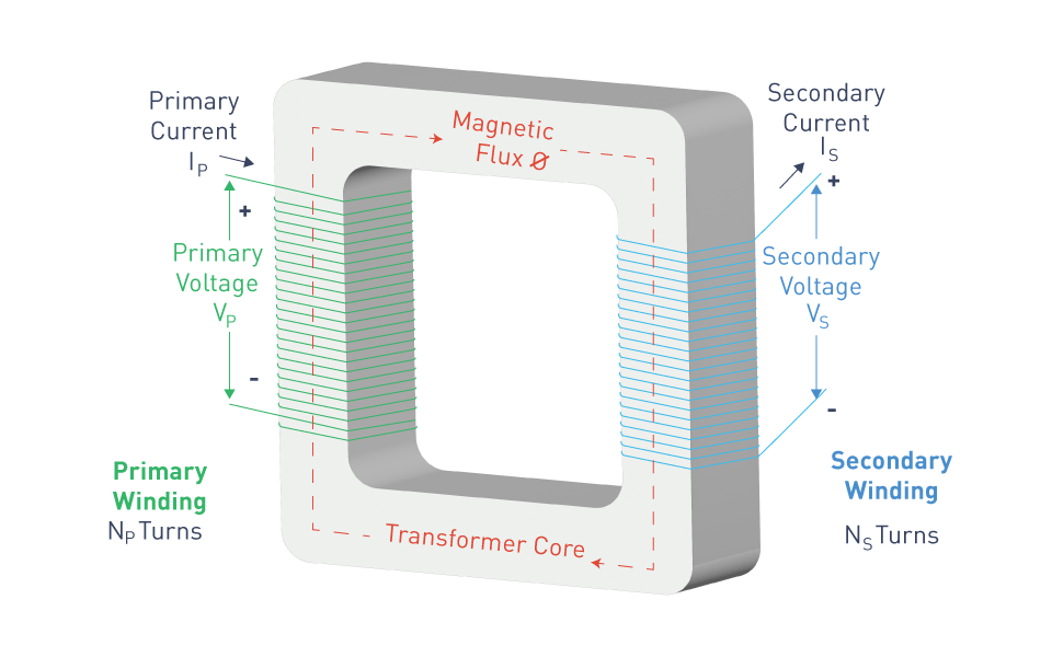
Figure 8: Transformer
Rectifier
A rectifier is an electrical device that transforms alternating current (AC) to direct current (DC). Rectifiers, which enable current to flow only in one way, are critical in the operation of power supply for electronic devices, battery charging, and large-scale power transmission networks. They range from straightforward diode circuits that produce a relatively pure DC output to intricate systems that convert AC to DC with considerable ripple.
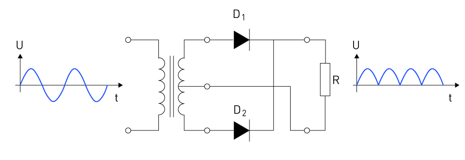
Figure 9: Full-wave rectifier
Inverter
An inverter is an essential part today's electrical systems; it is made to change direct current (DC) into alternating current (AC). It is the bedrock of many applications, such as renewable energy systems where DC electricity from solar panels or batteries must be converted to AC in order to work with the AC power grid or household appliances. Contemporary inverters are capable of managing grid connections, maximizing power production, and guaranteeing energy efficiency in addition to conversion. Intelligent controls are included in advanced inverters to support smart grid functions and ensure grid stability.

Figure 10: Inverter operation
Single-phase Power
An electrical power source with a single alternating current (AC) waveform is known as single-phase power. It is the typical power supply for residences and small businesses, offering a straightforward and efficient way to supply electricity for low-power appliances, heating, and lighting. Power is transferred through two wires in single-phase systems: a live (or hot) wire and a neutral wire. The voltage in these systems oscillates sinusoidally over time, alternating between a positive and a negative peak.
Three-Phase Power
Three alternating currents, each phase offset by one-third of the cycle (120 degrees), are used in three-phase power transmission. Large motors and heavy loads are popular uses for this system, which is more effective at distributing electricity than single-phase power in industrial applications. The three-phase method reduces transmission energy loss, permits lighter and thinner cables, and gives the equipment a steady power supply with less flicker and smoother performance.
Grid
The grid, or electrical grid, is the interconnected network that transports electricity from producers to consumers. It consists of producing stations that generate electricity, high-voltage transmission lines that transport power from far sources to demand centers, and distribution lines that connect individual customers. The grid also comprises substations, transformers, and control systems that regulate the flow of power to ensure that supply matches demand. Modern grids are turning into smart grids, which use digital technologies to improve efficiency, dependability, and sustainability.
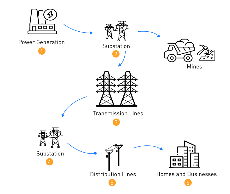
Figure 11: The electrical grid
Harmonics
Harmonics in electrical systems are voltages or currents that run at a multiple of the fundamental frequency, causing distortion in the power waveform. They are caused by non-linear loads such as variable-speed drives, tiny fluorescent lights, and other electrical equipment. Harmonics can create a variety of issues, including equipment overheating, nuisance tripping of circuit breakers, and decreased efficiency. Managing harmonics entails utilizing filters, developing systems to restrict their production, and adhering to regulations that establish allowed levels.
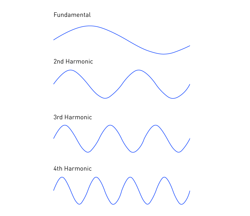
Figure 12: Harmonics
Load
A load is defined as any equipment or appliance that consumes electricity. It might vary from a single light bulb to sophisticated industrial apparatus. Loads are classified according to their nature (resistive, inductive, or capacitive) and the type of power required (AC or DC). Understanding the characteristics of various loads is critical for building electrical systems that can efficiently and securely supply power demands.
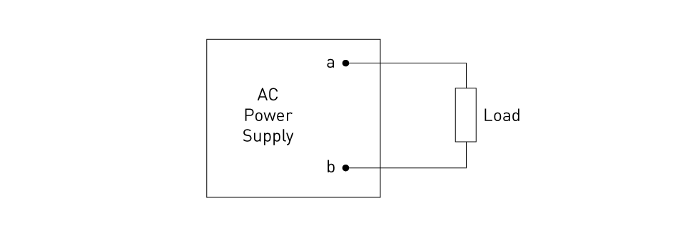
Figure 13: Load
Circuit Breaker
A circuit breaker is an automatically controlled electrical switch that protects an electrical circuit from harm caused by an overload or short circuit. Unlike a fuse, which only works once and must be replaced, a circuit breaker can be reset (manually or automatically) to restore normal operation. Circuit breakers are crucial components in homes, companies, and industrial buildings, protecting against the risk of fire and equipment damage caused by faulty wiring or device failures.
Resonance
In electrical circuits, resonance occurs when the stored energy oscillates between the magnetic field of the inductor and the electric field of the capacitor. At resonance, the circuit can produce substantial voltage and current oscillations, particularly at certain frequencies. While resonance can be used in applications such as filters, oscillators, and tuners, it can also cause undesirable effects and potential damage in power systems, necessitating careful design and control.
Isolation Transformer
An isolation transformer is a type of transformer that decouples two circuits, allowing AC power to be transferred from one device to another without requiring a direct electrical connection. This ensures safety by isolating the secondary circuit, reducing noise, and lowering the chance of shock. Isolation transformers are commonly employed in sensitive equipment, medical institutions, and applications requiring a clean and safe power supply.
Surge Protector
A surge protector protects electrical devices from voltage spikes. It restricts the voltage supplied to electrical equipment by blocking or shorting any voltages that exceed a safe threshold. Surge protectors are essential for safeguarding computers, entertainment systems, and other electronic equipment from damage caused by abrupt power surges such as lightning strikes, power outages, or grid-switching activities.
Generator (Alternator)
A generator, often known as an alternator in the context of alternating current power, is a device that converts mechanical energy into electrical energy using electromagnetic induction. It works by rotating a coil in a magnetic field to generate alternating current. Generators are critical components of power generation plants such as hydroelectric, thermal, and nuclear facilities, as they provide the initial source of electricity for grid distribution. They range in size from small portable emergency power units to large-scale industrial power generators.
Blackout
A blackout is a total disruption of power supply in a specific area, resulting in the loss of energy to homes, businesses, and other facilities. Blackouts can occur for a variety of reasons, including extreme weather, equipment failure, and electrical grid overloads. They can last anywhere from a few minutes to several days, greatly affecting communities and necessitating emergency response and restoration efforts from utility firms.
Brownout
A brownout is a momentary drop in voltage in the electrical power supply system that is purposely caused by utility companies to avoid overloading the grid. Brownouts, unlike blackouts, do not totally shut down power, but they can cause lights to dim and electrical equipment to perform less efficiently. Brownouts are employed as a preventive strategy to ensure grid stability and avoid a full-scale blackout during peak demand periods or emergencies.
Skin Effect
The skin effect is a phenomenon in alternating current (AC) transmission in which the current density is higher at the conductor's surface and decreases as depth increases. This effect becomes more pronounced at higher frequencies, thus reducing the cross-sectional area accessible for current flow while raising the conductor's resistance. The skin effect is an essential factor in the design of high-frequency AC circuits and power transmission systems, impacting the conductor size and material selection to maximize efficiency.
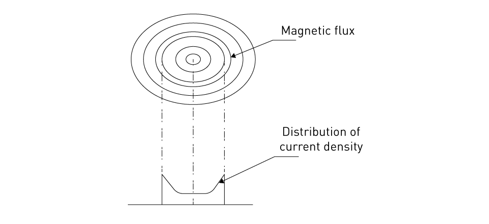
Figure 14: Skin effect on a conductor
Advantages of AC Over DC in Power Systems
In terms of electrical energy transmission and distribution, alternating current (AC) power systems outperform direct current (DC). These benefits are critical to the design and operation of contemporary power systems, providing efficient, dependable, and cost-effective electricity distribution to both industrial and residential consumers. When comparing AC to DC power systems, two major advantages stand out: efficient long-distance transmission and the use of transformers to adjust voltage levels.
Efficient Long-Distance Transmission
One of the most notable benefits of AC electricity is its efficiency in long-distance transmission. When electricity travels long distances, it suffers losses due to the resistance of the transmission lines, which causes some of the electrical energy to be dissipated as heat. AC power can be transmitted at high voltages and low currents to reduce losses, which DC power systems lack. High voltage transmission is beneficial as power loss in a conductor is related to the square of the current (P = I²R). By increasing the voltage (and hence decreasing the current) for transmission, AC systems significantly reduce energy loss, making long-distance electricity supply more practical and economically viable.
Additionally, the alternating nature of AC power enables the use of capacitors and inductors in the transmission network to manage power flow and increase system stability, which are not as readily available in DC systems.
Transformer Utilization for Voltage Level Changes
Transformers are key components of alternating current power systems because they allow for the efficient adjustment of voltage levels, which is required for both electrical power transmission and distribution. In an alternating current system, transformers may readily raise the voltage to a high level for long-distance transmission, decreasing power loss, and then lower the voltage to a safer, more useful level for industrial, commercial, and residential applications. This method is made feasible by electromagnetic induction, which works well with alternating current.
The ability to use transformers is a unique feature of AC systems, as transformer operation is dependent on the time-varying nature of AC. In contrast, DC electricity cannot be directly converted, necessitating the use of complicated and expensive converters to alter voltage levels. This constraint makes DC unsuitable for general power distribution grids that cover large areas and a diverse variety of consumption requirements.
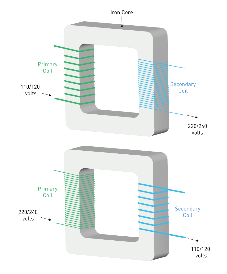
Figure 15: Step-up vs. step-down transformer


直接登录
创建新帐号