Grounding Electrodes
Grounding electrode systems are absolutely necessary in order to ensure electrical installations' security and stability. Because they establish a physical connection between an electrical system and the ground, they make it possible for fault currents to dissipate in a secure manner. When it comes to the efficiency of a grounding system, the selection of grounding electrodes and their subsequent installation are two crucial factors. Grounding electrodes can be broken down into three basic categories: rods, plates, and wires. Each of these categories has its own set of properties and applications.
Grounding Rods
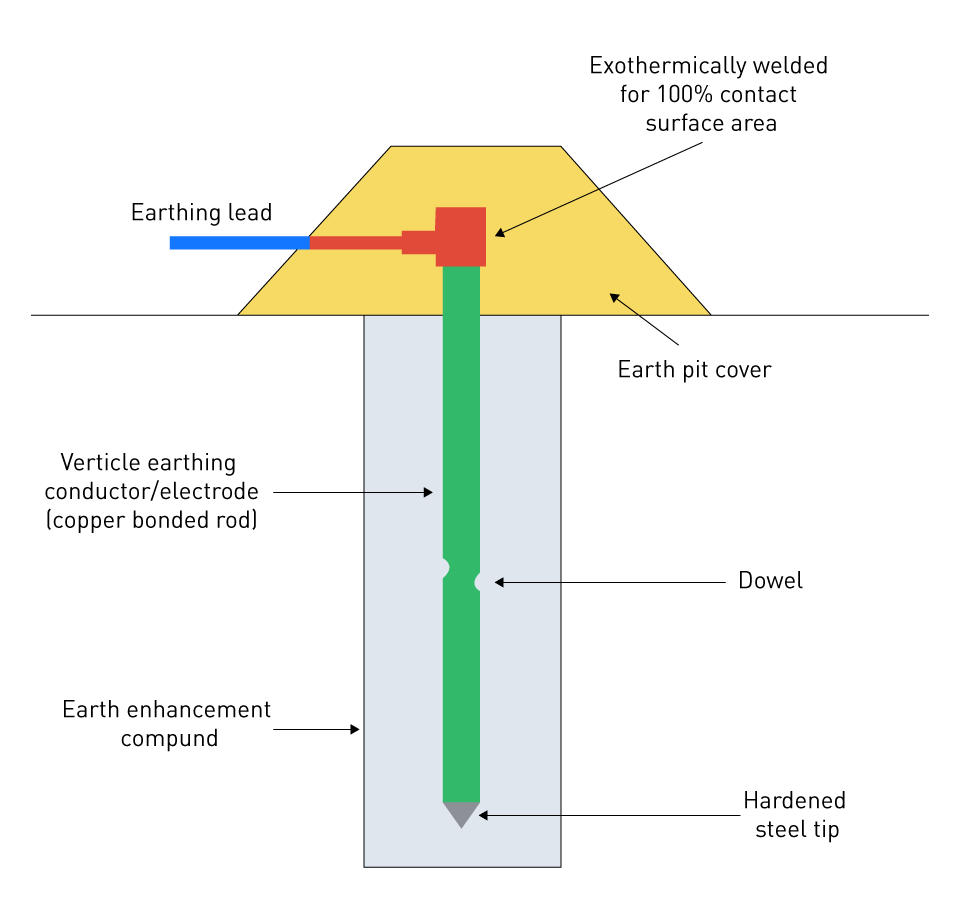
Description: Grounding rods are also known as ground rods or earth rods. They are long, conductive metal rods that are driven into the ground in order to make a direct electrical connection with the earth. Their other names include ground rods and earth rods. Copper, copper-clad steel, or galvanized steel are the most common materials used in their construction.

Figure 3: Ground rod inside Earthing pit
Characteristics:
Length and Diameter: In terms of length and diameter, grounding rods typically measure between 8 and 10 feet in length and have a diameter ranging from 5/8 to 3/4 inches. The soil resistivity and the requirements of the electrical system are taken into consideration while determining the length and diameter.
Material: Copper and copper-clad steel rods possess exceptional corrosion resistance and conductivity, rendering them highly suitable for a wide range of grounding applications. Rods made with galvanized steel are more cost-effective, but they may have a shorter lifespan due to corrosion-related issues.
Applications:
Residential and Commercial Installations: In residential and commercial installations, grounding rods are frequently employed to offer an efficient route for fault currents. This is because they are widely used in both residential and commercial buildings.
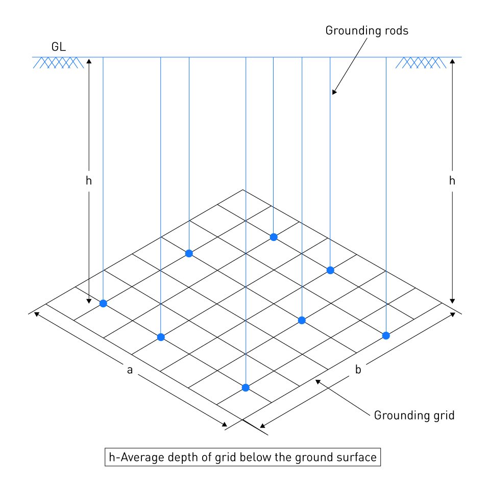
Substation Grounding: In the realm of electrical substations, it is possible to establish a grounding grid by interconnecting many grounding rods. This grid guarantees low-resistance grounding for high-voltage equipment.
Grounding Plates
Description: In order to give a wider surface area for contact with the soil, grounding plates are metal plates that are flat and conductive. These plates are buried in the ground above the ground. Most of the time, they are constructed out of galvanized steel or copper.
Characteristics:
Dimensions: Grounding plates typically measure around 2 feet by 2 feet, and their thickness is approximately 1/4 inch. It is possible for the size of the plate to change based on the grounding requirements and the conditions of the soil.
Material: In terms of material, copper plates are known for their exceptional conductivity and resistance to corrosion. On the other hand, galvanized steel plates are more cost-effective, but they have the potential to corrode over time.
Applications:
Difficult Soil Conditions: In regions where it is not feasible to drive rods into the ground due to the presence of rocky or hard soil conditions, grounding plates are introduced as a solution. The plate's slightly larger surface area ensures a sufficient amount of contact with the soil.
Supplementary Grounding: Supplementary grounding refers to the utilization of grounding plates in conjunction with other grounding electrodes, with the aim of enhancing the overall effectiveness of the grounding system.
Grounding Wires
Description: Grounding wires is also known as grounding conductors or grounding grids, and it helps establish a network of ground connections by burying conductive metal wires in trenches. Copper or steel that has been covered with copper is frequently used in their construction.

Figure 4: Grounding grid connected via grounding rods
Characteristics:
Configuration: Depending on the specific grounding requirements under discussion, one can organize grounding wires in a variety of configurations, such as radial, grid, or ring designs.
Material: Copper wires are highly favored due to their exceptional conductivity and resistance to corrosion. Copper-clad steel wires offer a compromise between pricing and performance in their construction.
Applications:
Large Installations: The use of grounding wires is particularly suitable for large installations, such as industrial plants, substations, and data centers, which necessitate the establishment of vast grounding networks to guarantee the safety and reliability of the system.
High-Performance Grounding: High-performance grounding is characterized by the ability to configure grounding wires in a flexible manner, which enables the creation of customized grounding solutions that are tailored to specific performance standards and site conditions.
Installation and Design Considerations
The installation and design of a grounding electrode system carry a significant amount of weight in determining how effective the system is. The depth and position of the electrodes, the characteristics of the soil, and the bonding needs are all important factors to take into consideration. It is imperative that each component be taken into consideration in order to guarantee the grounding system's safety, dependability, and overall performance.
Depth and Location
Depth:
Optimal Depth: When it comes to grounding electrodes, it is essential to ensure that they are set at an appropriate depth in order to guarantee a strong electrical connection with the earth. When it comes to rods, this often entails driving them between eight and ten feet into the landscape. It is recommended that plates and wires be buried at a depth of at least 2.5 to 3 feet in order to prevent fluctuations in the surface soil and to provide reliable grounding.
Soil Moisture and Temperature: Installations that are deeper typically reach soil layers that have a more stable moisture content and temperature. This, in turn, improves the grounding system's conductivity and effectiveness.
Location:
Proximity to Structures: It is important to ensure that grounding electrodes are situated in close proximity to the structure that they are safeguarding, while yet maintaining a sufficient distance to prevent any interference with foundations and other subsurface services. This proximity guarantees that there will be minimal resistance and that fault current will be effectively dissipated.
Avoiding Interference: The act of avoiding interference is of utmost importance, since it is imperative to avoid positioning electrodes in close proximity to subterranean pipes, wires, or metallic structures that have the potential to disrupt the functioning of the grounding system. Interference from electromagnetic waves has the potential to negatively impact the efficiency of the grounding system.
Soil Conditions
Soil Resistivity:
Measurement: When it comes to grounding systems, measurement of soil resistance is an essential aspect that significantly impacts their effectiveness. For example, soils with a high resistivity, such as sandy or rocky soils, require grounding solutions that are more comprehensive than those for soils with a low resistivity, such as clay or loam.
Improvement Techniques: It is possible to improve soil conductivity and enhance grounding efficacy by employing improvement techniques in high-resistivity areas. These approaches include adding moisture, utilizing chemical ground rods, or backfilling with conductive materials (for example, bentonite or conductive concrete).
Soil Composition and Corrosion:
Corrosive Environments: When soils possess high acidity, salinity, or other corrosive qualities, the selection of grounding electrode materials and protective coatings becomes of utmost importance. Materials that are resistant to corrosion, such as copper or steel that has been clad with copper, are preferable because they assure lifespan and dependability.
Soil Layers: One of the factors that can have an effect on grounding performance is the presence of different soil layers, each with a higher or lower resistivity. It is possible to maximize the effectiveness of grounding by either installing electrodes in the soil layer that is the most conductive or by employing multiple electrodes that are interconnected in different layers.
Bonding Requirements
In the field of electrical systems, bonding refers to the process of joining all of the metallic components to establish a continuous channel for the purpose of ensuring electrical continuity and safety. The purpose of this is to prevent potential differences between conductive parts and to guarantee that in the event of a malfunction, electrical current will have a path to ground that has a low resistance, hence lowering the risk of electric shock or fire.
Purpose of Bonding:
Safety: Safety is ensured via bonding, which guarantees that all metal pieces within an electrical system that do not transport current are at the same potential. This reduction in potential reduces the risk of electric shock and assures that fault current paths are safe.
System Integrity: The process of bonding ensures that there are no potentially hazardous voltage discrepancies between conductive components, hence improving the overall stability and performance of the system.
Bonding Techniques:
Conductors: In order to convey fault currents without subjecting them to excessive heat, bonding conductors need to be of a size and material that is sufficient. Copper and aluminum are two materials that are frequently employed because of their superior conductivity and sturdy nature.
Connections: Exothermic welding, mechanical connectors, and compression fittings are some of the recognized procedures that should be utilized to ensure the safety of all bonding connections before they are considered secure. Connections need to be inspected on a regular basis to guarantee that they continue to be secure and free of corrosion.
Main Bonding Jumper: The Main Bonding Jumper serves as the principal connection between the neutral conductor, which is grounded, and the grounding electrode system. It must be implemented in a secure manner and of an acceptable size in accordance with the specifications in order to preserve the integrity of the system.
Regulatory Compliance:
Standards: It is of utmost importance to adhere to standards such as the National Electrical Code (NEC) and the guidelines established by the International Electrotechnical Commission (IEC). These standards stipulate the bonding requirements to ensure both safety and performance.
Inspection and Testing: It is essential to conduct routine inspections and tests on bonding connections and grounding systems in order to ensure that they are in conformity with regulatory standards and to identify any potential flaws that could potentially jeopardize the effectiveness of the system.


直接登录
创建新帐号