Uncontrolled rectifiers are among the simplest AC/DC conversion circuits in power electronics. These circuits are called "uncontrolled" because they use uncontrolled power electronic components like diodes. Uncontrolled rectifiers convert AC to DC using diodes, which are passive electronic components that only allow current to flow in only one direction.
The most common forms of uncontrolled rectifiers are single-phase half-wave and full-wave rectifiers. Single-phase full-wave rectifiers are often employed in low-power applications where efficiency is not a major consideration. Three-phase full-wave rectifiers, on the other hand, are used in high-power applications with three-phase AC power available. Half-wave rectifiers are solely discussed for comparison. Center-tap rectifiers, bridge rectifiers, voltage doubler rectifiers, and voltage multiplier rectifiers are examples of uncontrolled rectifiers used in a variety of applications.
Filtering is essential in uncontrolled rectifiers because the output of these circuits often has a high level of AC ripple. The usage of filters, such as capacitors and inductors, reduces AC ripple and results in a more stable DC voltage output. Although uncontrolled rectifiers are less efficient than more sophisticated, controlled rectifiers, they are nevertheless an essential component of many power electronics systems due to their simplicity and reliability.
Single-Phase Half-Wave Rectifiers
Single-phase half-wave rectifiers are basic, uncontrolled rectifiers with simple designs. This circuit consists of a single diode and a load resistor linked in series to an alternating current source. During the positive half-cycle of the AC voltage, the diode is forward-biased and conducts current, which flows via the load resistor. But the diode gets reverse-biased during the negative half-cycle, which prevents any current from passing through the load resistor. Because of this, only half of the input AC waveform is being used, and the output voltage across the load resistor is pulsing DC.
The single-phase half-wave rectifier has various disadvantages, including a low efficiency of around 40%. This is because, during the negative half-cycle of the AC voltage, when the diode is not conducting, half of the input power is lost. Furthermore, the rectifier produces a large ripple voltage, which can cause problems for electronic gadgets.
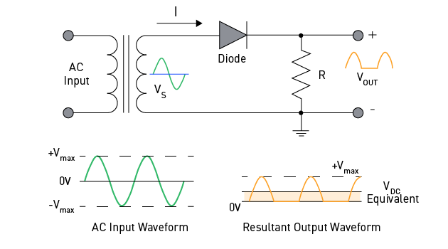
Figure 2: Digression: The efficiency of a half-wave diode rectifier
Assume that Vmax is the peak voltage across the resistor R
The average DC voltage is calculated with:
$$V_{dc} = \frac{1}{2\pi - 0} \left( \int_0^{\pi} V_{max} \sin x \, dx + \int_{\pi}^{2\pi} 0 \cdot dx \right)$$ $$\Leftrightarrow \quad V_{dc} = \frac{1}{2\pi} \int_0^{\pi} V_{max} \sin x \, dx$$ $$\Leftrightarrow \quad V_{dc} = \frac{1}{2\pi} V_{max} \left( -\cos(\pi) - (-\cos(0)) \right)$$ $$\Leftrightarrow \quad V_{dc} = \frac{V_{max}}{\pi}$$Thus:
$$I_{dc} = \frac{V_{max}}{R} \quad \frac{1}{\pi} = \frac{I_{max}}{\pi}$$The rms current in an AC circuit is calculated as with:
$$I_{rms} = \sqrt{\frac{1}{2\pi - 0} \left( \int_0^{\pi} I_{max}^2 \sin^2 x \, dx + \int_{\pi}^{2\pi} 0 \cdot dx \right)}$$ $$\Leftrightarrow \quad I_{rms} = \sqrt{\frac{1}{2\pi} \int_0^{\pi} I_{max}^2 \sin^2 x \, dx}$$ $$\Leftrightarrow \quad I_{rms} = \sqrt{\frac{I_{max}^2}{2\pi} \int_0^{\pi} \frac{1 - \cos(2x)}{2} \, dx}$$ $$\Leftrightarrow \quad I_{rms} = \sqrt{\frac{I_{max}^2}{4\pi} \left[ (\pi - 0) - \frac{1}{2} (\sin(2\pi) - \sin(0)) \right]}$$ $$\Leftrightarrow \quad I_{rms} = \frac{I_{max}}{2}$$The input AC power and output DC power are equal to:
$$P_{ac} = I_{rms}^2 \cdot (R_s + r_D + R)$$ $$P_{dc} = I_{dc}^2 \cdot R$$Where:
Rs is the resistance of transformer’s secondary winding.Rs
rDrD
RRR
The ratio of the DC power available at the load to the AC power input defines the efficiency of a half-wave rectifier:
$$\eta = \frac{P_{dc}}{P_{ac}} = \frac{I_{dc}^2 \cdot R}{I_{rms}^2 \cdot (R_s + r_D + R)} \approx \frac{I_{dc}^2 \cdot R}{I_{rms}^2 \cdot R} = \frac{\left(\frac{I_{max}}{\pi}\right)^2}{\left(\frac{I_{max}}{2}\right)^2} = \frac{4}{\pi^2} \approx 40.53\%$$The single-phase half-wave rectifier has some uses in tiny power supplies or circuits where cheap cost is essential and the output ripple voltage can be tolerated, despite its low efficiency and high ripple voltage.
Single-Phase Full-Wave Rectifiers
Single-phase full-wave rectifiers are more efficient than half-wave rectifiers since they generate a fully rectified output.
A transformer with a central tap and two diodes is used in one of the designs for full wave rectifiers. The diode connected to the upper end of the transformer conducts during the input voltage's positive half-cycle, while the diode connected to the lower end of the transformer conducts during its negative half-cycle. This causes an output voltage across the load resistor to be rectified to a full wave.
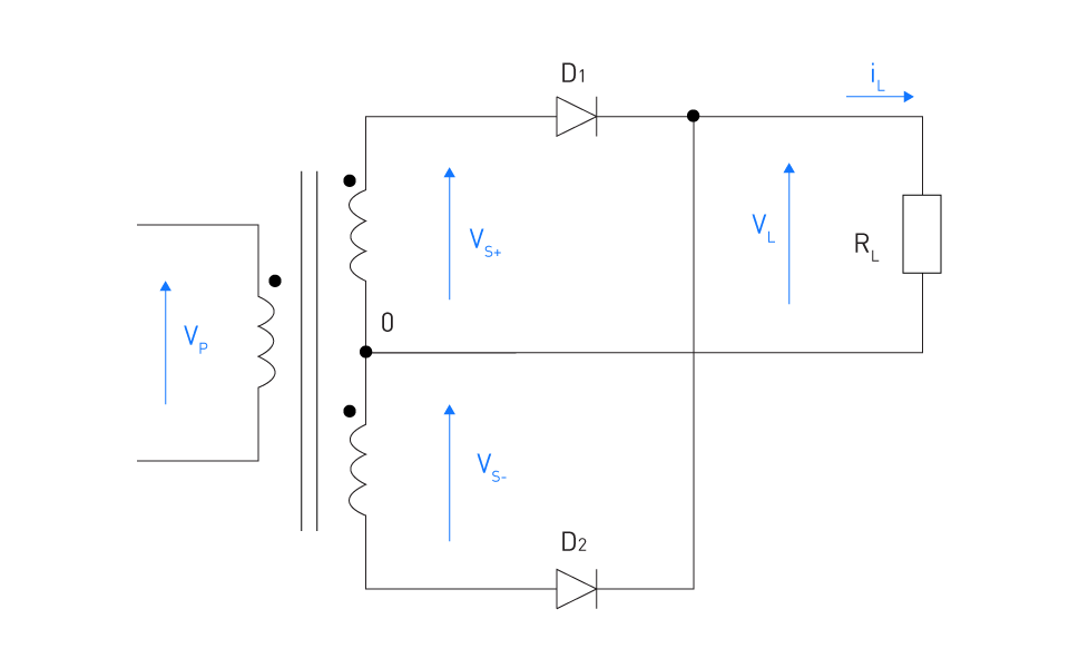
Figure 3: Single-phase full-wave rectifier - center-tapped
For both the negative and positive half-cycles of a full-wave rectifier, VL(t)=Vmax|sinωt|. Consequently, the output rms values for current and voltage are
$$V_L = \sqrt{\frac{1}{\pi} \int_0^{\pi} \left(V_{max} \sin x\right)^2 \, dx}$$Or
$$V_L = \frac{V_{max}}{\sqrt{2}} = 0.707 \, V_{max}$$And
$$I_L = \frac{V_L}{R} = \frac{0.707 V_{max}}{R}$$As seen in the following figure, the bridge rectifier is another topology for a single-phase full-wave rectifier.
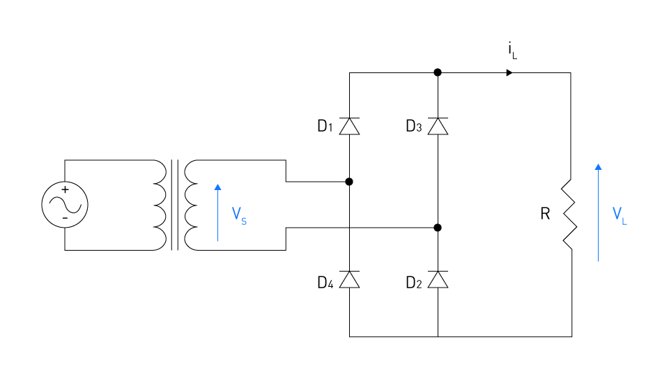
Figure 4: Bridge rectifier
During the positive half-cycle of the AC input voltage, the higher end of the transformer's secondary winding is positive compared to its lower end. Diodes D1 and D2 conduct current when they become forward biased. Due to their reverse bias, diodes D3 and D4 are non-conductive. This is the current path: AC source → D1 → R → D2 → AC source. A positive voltage is created across the load resistor R when current flows through it in one direction.
The higher end of the secondary winding is negative in relation to the lower end during the negative half-cycle of the AC input voltage. Forward-biased diodes D3 and D4 conduct current. Due to their reverse bias, diodes D1 and D2 are non-conductive. The current path is: AC source → D4 → R → D3 → AC source. Again, the load resistor gets current in the same direction as during the positive half-cycle, resulting in a positive voltage across it.
The bridge rectifier's voltage and current waveforms are shown in the figure below.
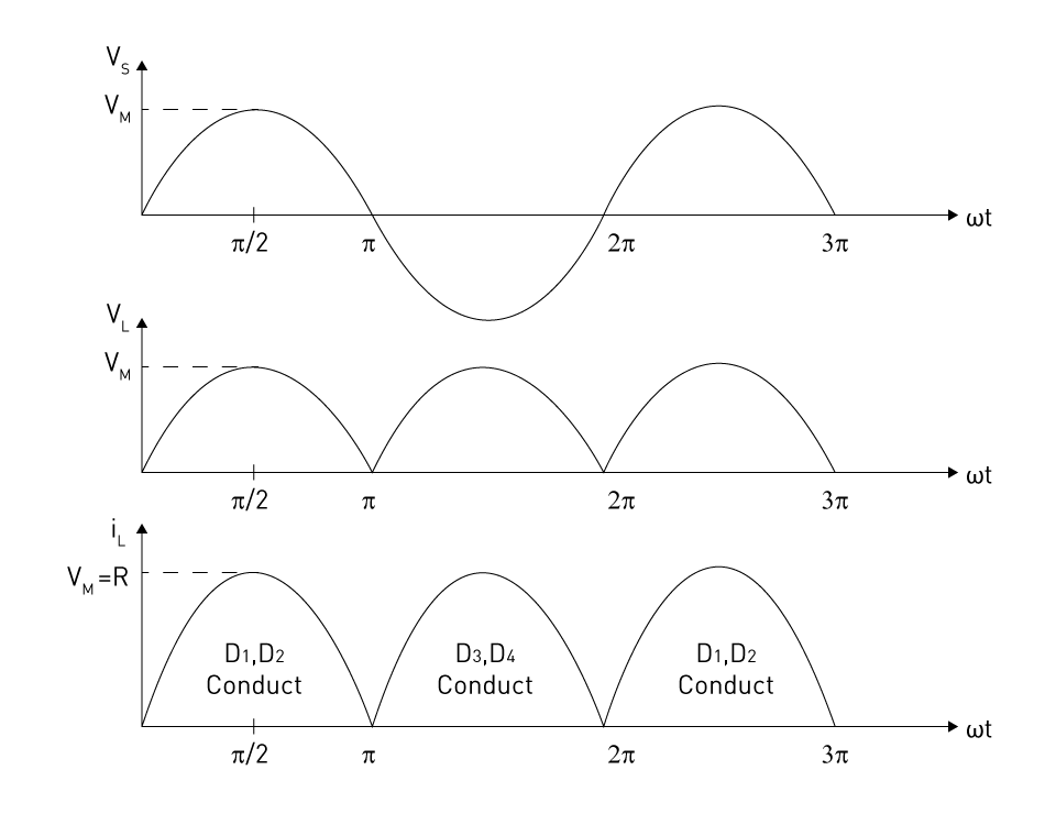
Figure 5: Voltage and current waveforms of the bridge rectifier
A single-phase full-wave rectifier produces twice as many output pulses for the same input frequency as a half-wave rectifier, resulting in a smoother and less rippled output voltage waveform. The ripple frequency is double the input frequency, allowing a capacitor filter to reduce ripple by half the value required for a half-wave rectifier. These rectifiers are widely used in low-power applications like battery chargers and small power supplies.
Three-Phase Half-Wave Rectifiers
Three-phase half-wave rectifiers are used in power electronics applications that need the conversion of three-phase alternating current to direct current. They are more efficient than their single-phase equivalents because they use all three phases of AC electricity. However, the output DC voltage still pulsates and requires further filtering to get a steady DC value.
The three-phase half-wave rectifier has the benefit of being simple, as it only requires three diodes. However, because only one of the three phases is employed at any given moment, the output voltage is lower than that of other types of rectifiers.
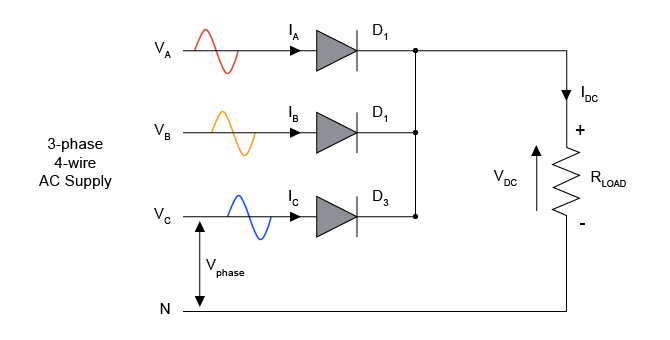
Figure 6: Half-Wave Three-Phase Diode Rectifier
Let us suppose that the phase voltage VA begins at 0°. During the time period of 0° to 30°, the voltage at the diode D3 anode is the maximum (VC > VA > VB). Thus, diode D3 conducts but diodes D1 and D2 do not. Thereafter, the voltage at the diode D1 anode reaches its maximum value between 30° and 150° (30°-90°: VA > VC > VB; 90°-150°: VA > VB > VC). Diodes D2 and D3 do not conduct, whereas diode D1 does. And so forth. The following graphic shows the voltage waveform at the rectifier's output (on the load).
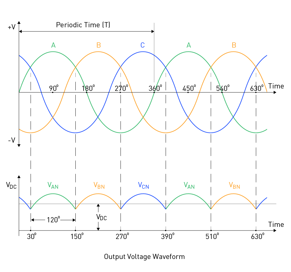
Figure 7: Output Voltage Waveform of Half-Wave Three-Phase Diode Rectifier
The average value of the output voltage waveform is as follows if we identify the peak input voltage as VP:
$$V_{DC} = \frac{3\sqrt{3}}{2\pi} V_P = 0.83 \cdot V_P$$This may restrict its application, especially in conditions where a greater DC voltage is necessary. Because it only requires three diodes, the three-phase half-wave rectifier is simpler and less expensive even if its output voltage is lower. Moreover, it results in high levels of harmonic distortion in the input current, which can lead to issues like higher electromagnetic interference and losses in power distribution and transmission networks. Therefore, it is crucial to take into account the trade-offs between the benefits and drawbacks of various rectifier types when developing power electronics systems.
Three-Phase Full-Wave Rectifiers
An unregulated three-phase diode rectifier circuit using a full-wave bridge design with six diodes is shown in Figure 8. The circuit's output is connected to a DC load, while its input is coupled to a three-phase AC power supply. The following describes how the circuit operates.
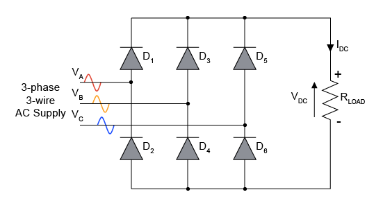
Figure 8: Uncontrolled Full-Wave Three-Phase Diode Rectifier
Assuming that the phase A voltage begins at 0°, as shown in the figure below.
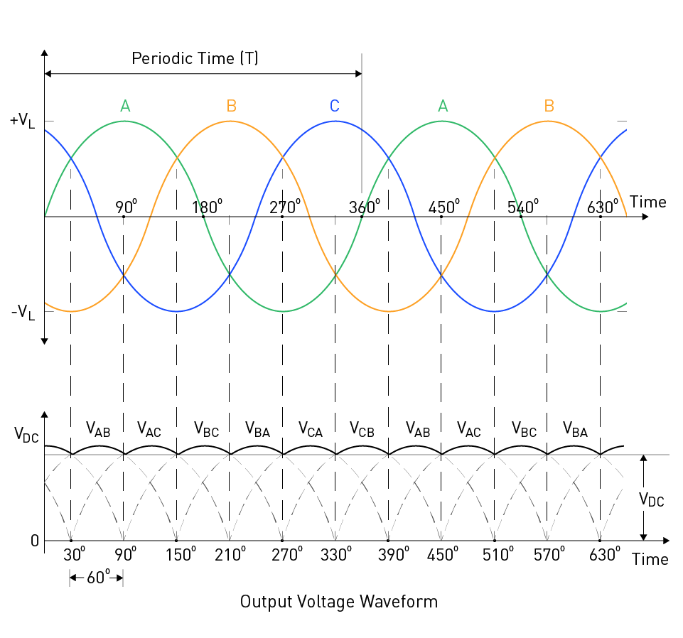
Figure 9: Output Voltage Waveform of Full-Wave Three-Phase Diode Rectifier
Time period from 0° to 30°
VC > VA > VB ⇒ Diodes D5 and D4 are ON
Diode D1 is OFF (Anode voltage VA is lower than cathode voltage VC)
Diode D2 is OFF (Anode voltage VB is lower than cathode voltage VA)
Diode D3 is OFF (Anode voltage VB is lower than cathode voltage VC)
Diode D6 is OFF (Anode voltage VB is lower than cathode voltage VC)
So, the load voltage is equal to: Vload = VC - VB
Time period from 30° to 90°
VA > VC > VB ⇒ Diodes D1 and D4 are ON
Diode D2 is OFF (Anode voltage VB is lower than cathode voltage VA)
Diode D3 is OFF (Anode voltage VB is lower than cathode voltage VA)
Diode D5 is OFF (Anode voltage VC is lower than cathode voltage VA)
Diode D6 is OFF (Anode voltage VB is lower than cathode voltage VC)
So, the load voltage is equal to: Vload = VA - VB
And so forth. The above figure shows the waveform of the voltage at the rectifier's output (on the load).
The average output value can be calculated with the following equation:
$$V_{DC} = V_P \cdot \frac{3\sqrt{3}}{\pi} = 1.654 \cdot V_P$$Other Single-Phase Rectifier Types
Power electronics systems use a variety of uncontrolled rectifiers, including the center-tapped rectifier and the bridge rectifier.
The voltage doubler rectifier is yet another type of uncontrolled rectifier used in applications that require a larger DC voltage output than a standard rectifier. This rectifier uses two diodes and two capacitors to boost the output voltage of a single-phase alternating current source. Other uncontrolled rectifier topologies, such as the Cockcroft-Walton multiplier for high-voltage DC applications and the Graetz circuit for high-power DC applications, are also used in some specific applications. These rectifiers produce high-power or high-voltage DC outputs by combining diodes and capacitors. No matter what kind of unregulated rectifier is used, filtering is usually necessary to reduce the ripple voltage in the output waveform. Use inductors, capacitors, or both to reduce ripple voltage and smooth out the output waveform.
Filtering
Filtering is a significant factor to consider when developing uncontrolled rectifiers since it helps smooth out the output voltage and reduces ripple voltage. The pulsing nature of the rectified AC signal causes tiny changes in the output voltage waveform, known as ripple voltage. These variances can cause concerns such as reduced accuracy in electronic systems, increased electromagnetic interference, and lower reliability of electronic components.
Using a capacitor filter is a popular method for reducing voltage ripple. One capacitor connected in parallel with the load resistance constitutes a capacitor filter. The capacitor will store charge and absorb energy from the circuit as the voltage increases. On the other hand, the capacitor will release its stored energy into the circuit when the voltage across the load resistor drops, preventing the voltage from dropping too low. The capacitance value of the filter capacitor determines the degree of ripple reduction; higher capacitance values result in better filtering performance.
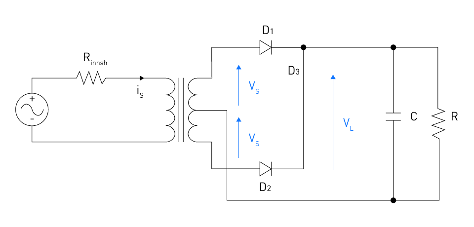
Figure 10: Full-wave rectifier with capacitor-input DC filter
The last option is to use an LC filter, which is a combination of an inductor and a capacitor filter. Although LC filters are more difficult to design and install, they provide superior filtering performance as compared to utilizing only capacitor or inductor filters. Based on particular application requirements, such as the necessary level of ripple reduction, cost, and physical size restrictions, the filter type and design are selected.
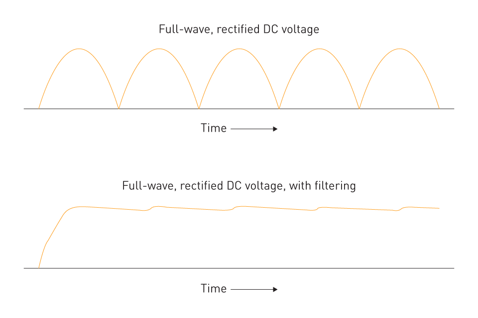
Figure 11: The effect of filtering on ripple


直接登录
创建新帐号