Single-Phase Controlled Rectifiers
Phase-controlled rectifiers are power electronics circuits that convert alternating current (AC) voltage to direct current (DC) voltage by adjusting thyristor firing angles. Thyristors are semiconductor devices that can control the flow of current using a gate signal. Motor drives, heating and lighting control, battery chargers, and electronic device power supply are among applications that use phase-controlled rectifiers.
One thyristor is used by a single-phase controlled rectifier, a type of phase-controlled rectifier, to regulate the flow of electricity. Single-phase controlled rectifiers allow current to be regulated in both directions, in contrast to diode rectifiers that only let current to flow in one direction. The load can be powered down by controlling the output voltage and current by adjusting the thyristor's firing angle. Battery chargers and AC motor speed control are two common applications for single-phase controlled rectifiers.
In power electronics applications, single-phase controlled rectifiers, sometimes referred to as phase-controlled rectifiers, are essential components. With the capacity to regulate the output voltage, these devices are used to convert alternating current (AC) to direct current (DC). This is accomplished by varying the firing angle, also known as the phase angle, of thyristors, which are semiconductor devices with high current switching capacity.
Half-Wave Controlled Rectifiers
The single thyristor used in a half-wave-controlled rectifier is connected in series with the load. The thyristor conducts when it is activated at a certain firing angle during the positive half-cycle of the input AC supply. The firing angle and the input AC voltage amplitude determine the output voltage waveform. The amount of power supplied to the load can be regulated by varying the firing angle, which also influences the average output voltage. The drawback of half-wave-controlled rectifiers is that they only use half of the AC waveform that is input, which leads to low power factor and significant harmonic distortion.
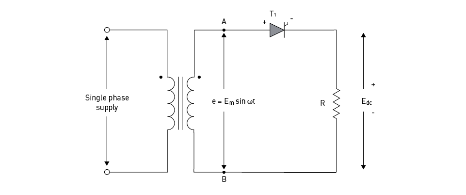
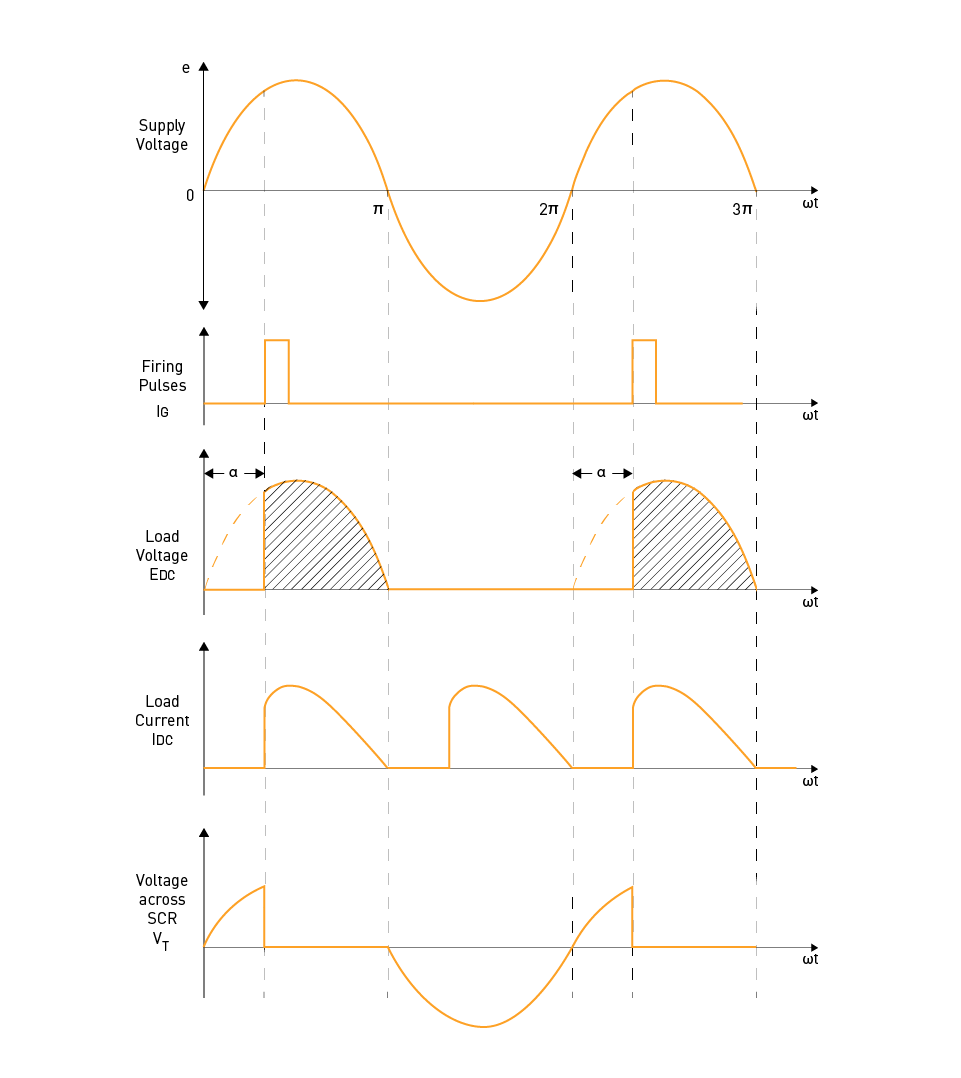
Figure 12: Single-phase half-wave controlled rectifier circuit (top) and waveforms (bottom)
Full-Wave Controlled Rectifiers
Full-wave-controlled rectifiers use two or more thyristors and are more efficient than their half-wave equivalents. These rectifiers use both the positive and negative half-cycles of the input AC supply. There are two basic types of full-wave-controlled rectifiers: midpoint and bridge configurations.
1. Midpoint Configuration:
A center-tapped transformer and two thyristors are used in the midpoint or center-tapped configuration. The transformer's secondary winding is divided in half, with the load connected to the midpoint of the winding. The thyristors are connected to the terminals of the secondary windings and the load. By sequentially activating the thyristors, the rectifier conducts during both the positive and negative half-cycles of the input AC supply, allowing the firing angle to be adjusted to regulate output voltage. However, one downside of this setup is that it requires a center-tapped transformer, which can be expensive and complicated.
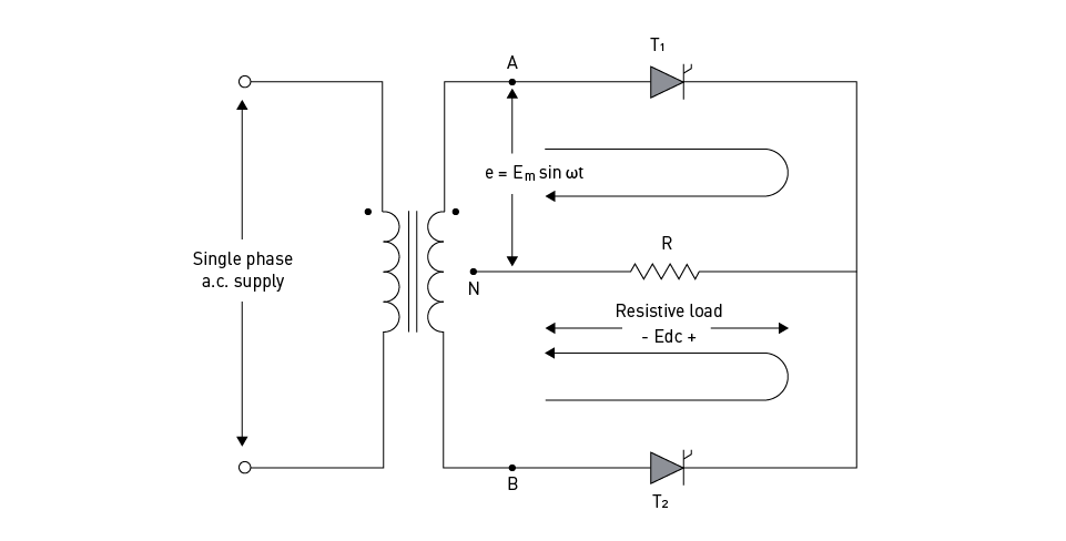
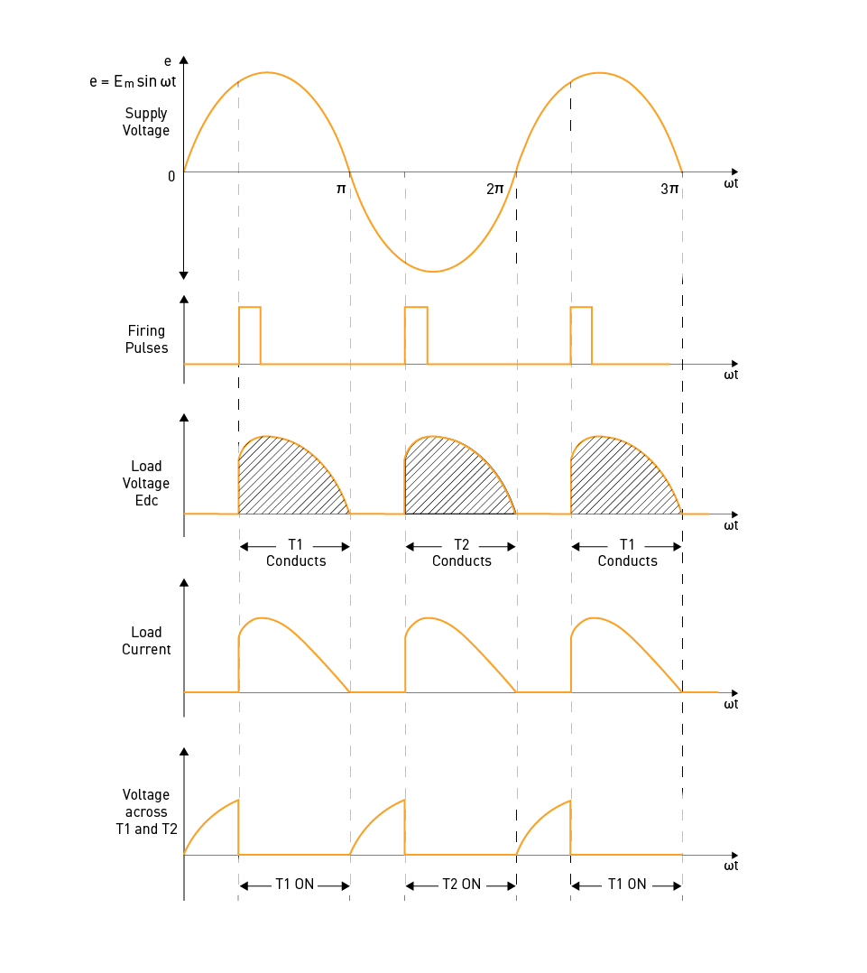
Figure 13: Single-phase full-wave controlled rectifier with midpoint configuration - circuit (top) and waveforms (bottom)
2. Bridge Configuration:
The bridge configuration is a phase-controlled rectifier with four thyristors organized in a bridge topology. This removes the requirement for a center-tapped transformer, resulting in a more compact and cost-effective design. In the bridge configuration, two diagonally opposing thyristors conduct during the positive half-cycle, while the other two thyristors conduct during the negative half. The output voltage can be adjusted by altering the thyristor firing angles. Bridge rectifiers have various advantages over the midpoint configuration, including increased efficiency, improved power factor, and lowered harmonic distortion.
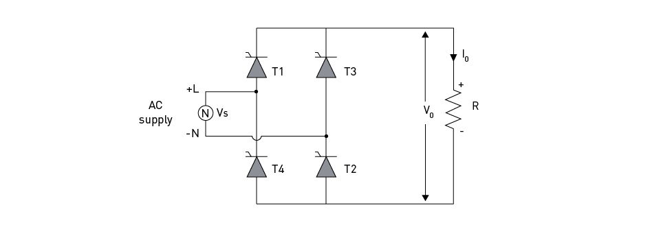
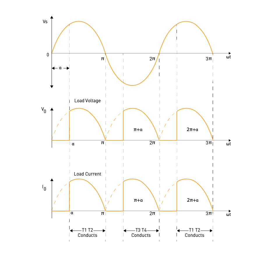
Figure 14: Single-phase full-wave controlled rectifier in the bridge configuration - circuit (left) and waveforms (right)
Performance Parameters and Control Techniques
A single-phase controlled rectifier's performance is evaluated using metrics including total harmonic distortion, power factor, ripple factor, average output voltage, and output current. The firing angle can be changed via integral cycle control, pulse-width modulation, and constant firing angle control.
Constant Firing Angle Control: By using a technique called constant firing angle control, the firing angle of the thyristors is maintained constant during the rectification process. This method provides an easy way to control the average output voltage. That may, however, result in problems with harmonic distortion and power factor, particularly at lower output voltage levels.
Integral Cycle Control: Integral cycle control involves turning the thyristors on and off for a predetermined number of full input voltage cycles in order to regulate the output voltage. Harmonic distortion can be decreased and the power factor can be raised with this technique. Significant output voltage and current ripples, on the other hand, can also result from it, which in some applications could have unintended effects and additional noise.
Pulse-Width Modulation: Pulse-width modulation (PWM) is a sophisticated control technique that dynamically changes the firing angles of thyristors to generate a desired output voltage waveform. By carefully adjusting firing angles, PWM can decrease harmonic distortion, enhance power factor, and offer better output voltage control. PWM-controlled rectifiers, on the other hand, need more sophisticated control circuitry, and perhaps require advanced digital controllers or microprocessors.
Applications of Single-Phase Controlled Rectifiers
Single-phase controlled rectifiers are widely used in many different applications, such as electric car charging stations, variable-speed motor drives, battery charging, and power supply for electronic devices. These rectifiers can handle large power levels and control the output voltage, making them appropriate for a wide range of commercial, industrial, and domestic applications.
In conclusion, it is important to mention that single-phase controlled rectifiers are frequently employed in power electronics due to their capacity to effectively and accurately convert AC power to DC power. Engineers can utilize their understanding of operating principles, performance parameters, and control techniques to build and implement these devices in a variety of applications. As technology and control strategies progress, single-phase controlled rectifiers will continue to play an important role in addressing the needs of modern electrical systems.
Semi/Dual/Full/Series Converters
Single-phase controlled rectifiers are grouped into various types based on the converters used to control the output voltage. These categories include semi-converters, dual, full, and series converters.
A specific DC-output current and voltage combination of a rectifier represents the coordinates of an operating point in the plane, and all permitted operating points create an operating area. A controlled rectifier can only function in the first and fourth quadrants, but diode rectifiers (or uncontrolled rectifiers) can only operate in the first.
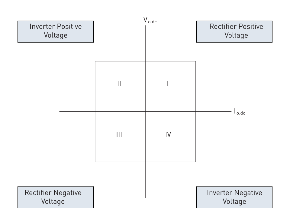
Figure 15: Four quadrants of rectifier operation
1. Single-Phase Dual Converters:
Dual converters are single-phase controlled rectifiers that can supply positive and negative half-cycles of the input voltage to the load. This gives them greater versatility than half-wave converters. Dual converters consist of two converters, one acting as a rectifier and the other as an inverter, allowing them to be employed in applications requiring bidirectional power flow. Furthermore, dual converters are especially built for four-quadrant operation and are widely utilized in reversible and variable-speed DC drives.
The first quadrant is for forward driving, with the thyristors' firing angle being less than 90 degrees and converter 1 turned on in rectifier mode. When converter 2 is in inverter mode and the thyristors' firing angle is larger than 90 degrees, the second quadrant is used for regenerative braking. In the third quadrant, which is designated for reverse motoring, the thyristors' firing angle is less than 90 degrees and converter 2 is turned on in rectifier mode. Additionally, the fourth quadrant—where converter 1 is turned on in inverter mode and the thyristor firing angle is larger than 90 degrees—is used for regenerative braking.
Although dual converters offer greater adaptability and bidirectional power flow, their more complicated design and component needs make them more expensive and sophisticated than semi-converters and single-phase full-wave controlled rectifiers. Furthermore, dual converters can generate larger levels of harmonic distortion in the input current, resulting in higher power losses in transmission and distribution systems, as well as electromagnetic interference challenges. Thus, careful consideration of the trade-offs between different rectifier types is essential for building efficient and high-performance power electronics systems.
2. Single-Phase Semi-Converters:
A single-phase semi-converter consists of two thyristors (SCRs) and two diodes. When activated, SCRs function as solid-state switches, allowing current to flow in only one way. These devices are also called thyristors. In a single-phase semi-converter, one diode and one SCR regulate the positive half-cycle of the AC input voltage, while the second diode and SCR regulate the negative half-cycle. Controlling the timing of the trigger pulses to the SCRs allows you to modify the average DC voltage given to the load. The conduction angle of the SCR refers to the time when the thyristor is forward-biased and conducts current. The conduction angle is determined by the timing of the thyristor trigger pulse relative to the zero-crossing point of the AC waveform, which can be adjusted to regulate the average DC voltage supplied to the load.
Semi-converters, which use two SCRs and two diodes, provide a simple and effective method for controlling the DC voltage supplied to a load. However, their output voltage is restricted to 64% of the peak input voltage (discussed in detail below), and the average DC voltage given to the load is less than that of a full-wave rectifier.
Where the firing angle of an SCR is denoted as α and the peak input voltage is indicated as VP, the average output voltage is equal to:
$$V_{\text{DC}} = \frac{V_{\text{P}}}{\pi} \left( 1 + \cos{\alpha} \right)$$Hence, the maximum output voltage is:
$$V_{\text{DC\_max}} = \frac{2 \cdot V_{\text{P}}}{\pi} \approx 0.64 \cdot V_{\text{P}}$$Forward motoring in the I quadrant is the sole quadrant action that a single-phase semi-converter can perform. When developing power electronics systems, careful analysis of the trade-offs between various rectifier types is necessary to achieve maximum performance and efficiency.
3. Single-Phase Full Converters:
Four SCRs are used by single-phase full converters to provide a steady DC output voltage. Similar to dual converters, full converters give bidirectional power flow and offer a constant output voltage. The full converter can provide a constant output voltage for both the positive and negative half-cycles of the AC input voltage by implementing four SCRs.
A full converter has two quadrants: forward motion (I) and reverse braking (IV). During forward motion, the input voltage is supplied to the load using the same polarity as the output voltage. During reverse braking, the input voltage is supplied to the load in the opposite polarity as the output voltage, allowing the load to release energy as heat or return it to the power source. This makes full converters appropriate for applications such as DC motor drives, which require bidirectional power flow for motoring and braking operations.
A single-phase full converter operates in two quadrants: the first (I) for forward drive and the fourth (IV) for reverse braking. During the first quadrant operation, the input voltage is applied to the load in the same polarity as the output voltage, but during the fourth quadrant operation, the input voltage is applied in the opposite polarity as the output voltage. For bidirectional power flow applications, such as DC motor drives, where both motoring and braking actions are required, full converters are perfect because they enable the load to either return energy to the power source or dissipate energy as heat.
Full converters provide bidirectional power flow as well as a constant output voltage, but they require four SCRs and extra control circuits. Full converters can produce larger amounts of harmonic distortion in the input current, resulting in increased power losses and electromagnetic interference. As a result, while developing power electronics systems, it is critical to carefully consider the trade-offs between various types of rectifiers in order to obtain maximum effectiveness and reliability.
4. Single-Phase Series Converters:
To generate both positive and negative output voltages, series converters combine semi-converters and dual converters. They are made up of a dual converter coupled in series with two semi-converters. Applications requiring precise output voltage control and high power are frequently utilized using series converters.
Three-Phase Controlled Rectifiers
In power electronics, three-phase controlled rectifiers are a common component that are used to convert three-phase AC power to DC power. These rectifiers are used in many different industries, including motor controllers, variable-speed drives, and power supply. The basic design of a three-phase controlled rectifier consists of six thyristors arranged in a bridge topology to control the rectifier's output voltage.
Six-Pulse Full-Wave Controlled Rectifiers
Six-pulse and twelve-pulse rectifiers are the two primary types of three-phase controlled rectifiers. Rectifiers with six pulses are the most basic and widely utilized. In each phase of the rectifier circuit, they have three thyristors linked in series, and when they fire one after the other, the result is a pulsed output voltage. A filter capacitor is then used to smooth the output voltage, providing a DC voltage.
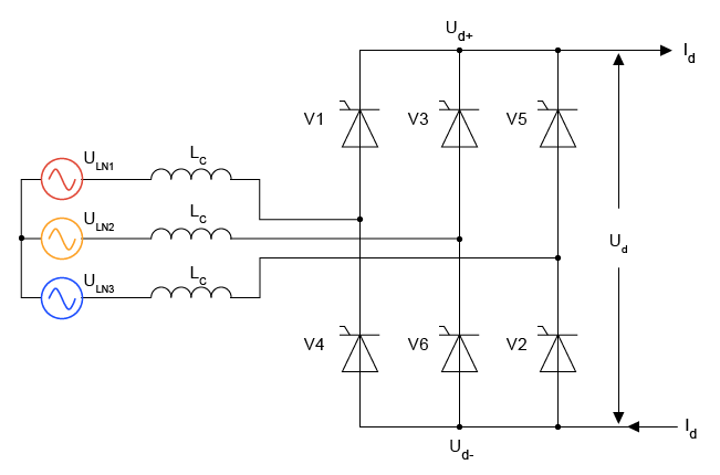
Figure 16: Three-Phase 6-Pulse Full-Wave Controlled Rectifier
Twelve-Pulse Full-Wave Controlled Rectifiers
Twelve-pulse rectifiers, on the other hand, are made up of two six-pulse rectifiers coupled in parallel to create a more consistent DC output voltage. To synchronize the two rectifiers, they need a more complicated control system.
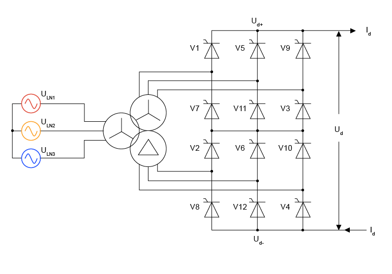
Figure 17: Three-Phase 12-Pulse Full-Wave Controlled Rectifier
Compared to single-phase controlled rectifiers, three-phase controlled rectifiers provide a number of benefits, such as improved efficiency, less harmonic distortion, and increased power output. They do, however, need a more advanced control system due to their complexity. Furthermore, they need more semiconductor switches, which raises the rectifier circuit's total cost.
Input Current Harmonic Distortion
Three-phase controlled rectifiers are extensively used in industrial applications due to their capacity to deliver adjustable DC voltage and adjustable power. However, the input current harmonic distortion of these rectifiers is a serious drawback. Because of the non-linear nature of the rectifier circuit, the input current contains harmonics that can create power system disruptions and affect the operation of other connected devices. The total harmonic distortion (THD) factor can be used to assess input current harmonic distortion. The THD factor is equal to the root-mean-square (RMS) value of the input's harmonic content divided by the RMS value of the fundamental frequency component.
$$\text{THD} = \frac{\sqrt{\sum_{n=2}^{\infty} V_n^2}}{V_1} \times 100\%$$Where
- The RMS value of the nth harmonic component of the voltage is denoted by Vn.
- The RMS value of the fundamental component of the voltage is V1.
Harmonic injection, pulse skipping, and space vector modulation are some of the control strategies that can be used to reduce input current harmonic distortion in three-phase controlled rectifiers. Because a high THD factor can cause voltage distortion, reduce power quality, and increase power losses, it is critical to minimize it in order to improve power system performance and reliability.
Output Ripple Voltage
The term output ripple voltage in three-phase controlled rectifiers describes the deviation of the DC output voltage from the desired constant value. This deviation is brought about by the pulsing character of the rectified output waveform, which is produced by the switching action of the thyristors.
In three-phase controlled rectifiers, the frequency of the AC input voltage and the load current are exactly proportional to the amplitude of the output ripple voltage. The amplitude of the output ripple voltage will thus grow in parallel with an increase in the load current or a decrease in the frequency of the input voltage. The overall quality of the DC output voltage is decreased by this rise in ripple voltage.
Three-phase controlled rectifiers use a variety of methods, including capacitive, inductive, and LC filtering, to lower the output ripple voltage. These filtering methods reduce the magnitude of the output ripple voltage and smooth out the pulsing DC output waveform by using passive components like capacitors and inductors.
The particular application and needed amount of ripple reduction determine which filtering approach is best. While capacitive filtering is an easy and affordable solution, its ability to reduce higher-order harmonics is limited. Higher-order harmonics can be reduced more successfully with inductive filtering, but the process is more complex and costly. LC filtering has the highest amount of ripple reduction, but it is also the most complex and costly filtering technique. Reducing output ripple voltage is critical for achieving a stable and consistent DC output voltage in three-phase controlled rectifiers. The use of filtering techniques can successfully reduce the amplitude of the output ripple voltage while improving the overall quality of the DC output voltage.
Efficiency
Efficiency is a key factor in the design and operation of three-phase controlled rectifiers. The rectifier efficiency is calculated as the ratio of DC output power to total input power.
$$\eta = \frac{P_{\text{DC}}}{P_{\text{AC}}} \times 100\%$$Where
- PDC denotes the DC power output.
- PAC denotes the AC power input.
Several factors can affect efficiency in three-phase controlled rectifiers, including the control strategy employed, load characteristics, and switching frequency.
The maximum rectifier efficiency is typically attained when the output voltage and current are consistent and losses are minimized. However, in real-life applications, the output voltage and current may not be constant, and the rectifier may lose power owing to switching, conduction, and other causes. To increase efficiency, it is vital to eliminate losses in the rectifier circuit.
Using a high-frequency switching strategy, such as pulse-width modulation (PWM) control, can reduce switching losses and improve rectifier efficiency, resulting in lower losses. Furthermore, employing soft-switching techniques, like as resonant switching, can reduce voltage and current stresses on switching devices while increasing overall rectifier efficiency.
It is vital to note that the efficiency of a three-phase controlled rectifier might vary depending on the load circumstances. For example, idle losses in the circuit can drastically diminish efficiency under low load conditions. To maximize the efficiency of three-phase controlled rectifiers, load conditions must be considered while designing and operating them.
Semi/ Dual / Full / Series Converters
1. Three-Phase Semi-Converters
Three-phase semi-converters, also known as half-controlled converters, use both diodes and thyristors to correct three-phase alternating current voltage. These converters have a bridge configuration comprising of three diodes and three thyristors. It is possible to regulate the current passing through the load by firing the thyristors at a certain angle, α. Applications requiring unidirectional power flow with an inductive load, such battery chargers and DC motor drives, frequently employ semi-converters.
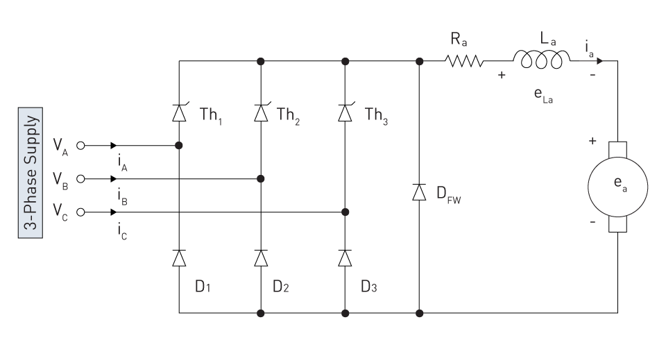
Figure 18: Three-phase semi converter
Three-phase semi-converters provide the following advantages:
- lower total cost due to simpler circuitry than full converters.
- less harmonics and a smoother output voltage waveform than single-phase converters.
On the other hand, the discontinuous output current of three-phase semi-converters can necessitate further filtering.
2. Three-Phase Full-Converters
Unlike semi-converters, three-phase full-converters employ six thyristors arranged in a bridge configuration to offer complete control over the rectification procedure. It is possible to accurately regulate the output voltage by varying the thyristors' firing angle. These converters are perfect for high-power battery chargers, variable-frequency drives, and regenerative braking systems, among other applications that need precise voltage control and bidirectional power flow.
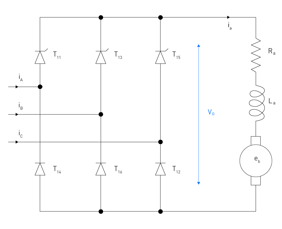
Figure 19: Three-phase full converter
Three-phase full converters offer the following advantages:
- Constant and controllable output current.
- Improved control over output voltage and power factor.
- Bidirectional power flow improves efficiency.
On the other hand, full-converters need more sophisticated control circuitry and have a greater harmonic content than semi-converters.
3. Three-Phase Dual-Converters
Three-phase dual-converters are made up of two three-phase full-converters that can be coupled in parallel or series to operate in four quadrants. This configuration allows the converter to manage both the magnitude and polarity of the output voltage, making it excellent for applications needing quick direction reversal or dynamic torque control, such as big cranes, elevators, or electric vehicles.
Three-phase dual converters offer the following advantages:
- Greater control over motor speed and torque is possible with four-quadrant operation.
- Bidirectional power flow enables regenerative braking systems to recover energy.
- increased dynamic responsiveness as a result of voltage and polarity being independently controlled.
Three-phase dual-converters are appropriate for high-performance applications where precise control and quick reaction are crucial, but they are more complicated and costly than other kinds of controlled rectifiers.


直接登录
创建新帐号