Introduction to Three-Phase AC/AC Converters
Three-phase adjustable current/alternating current converters are used to convert and regulate the RMS voltage and frequency in three-phase alternating current (AC) electrical systems. Wide-ranging industrial applications commonly utilize them due to their capacity to handle larger power levels, increased dependability, and superior performance compared to single-phase AC/AC converters. Motor drives, uninterruptible power supplies (UPS), and large-scale power systems are examples of applications that are suitable for three-phase AC/AC converters because of their ability to perform heavy-load applications.
Maintaining the input frequency while simultaneously adjusting the RMS magnitude and/or phase angle of the output voltage is the primary objective of three-phase AC/AC converters. These devices can be classified into two distinct categories: three-phase AC voltage controllers and three-phase AC choppers. Both types of converters use power electronic switches such as Insulated Gate Bipolar Transistors (IGBTs), Metal-Oxide Semiconductor Field-Effect Transistors (MOSFETs), and Thyristors to modify the output voltage waveform.
In this section, we will discuss the fundamentals of operation, the different types of loads, the control methods, the approaches for controlling voltage, and the applications of three-phase AC voltage controllers and three-phase AC choppers. By gaining an understanding of the fundamental concepts and characteristics of three-phase AC/AC converters, students and engineers can be better equipped to design and implement power electronic systems that are reliable and efficient for a wide range of applications.
Three-Phase AC Voltage Controllers
In order to manage the root-mean-square (RMS) and phase angle of the output voltage, three-phase AC voltage controllers are power electronic converters that change the firing angle of the power semiconductor switches. Thyristors or triacs serve as the primary switching devices in these controllers. Various topologies, including antiparallel and series, connect these devices. The operation of a three-phase AC voltage controller is based on the notion of phase control, which involves modifying the firing angle of each thyristor in order to govern the conduction time and, as a consequence, the waveform of the output voltage.
Principle of Operation
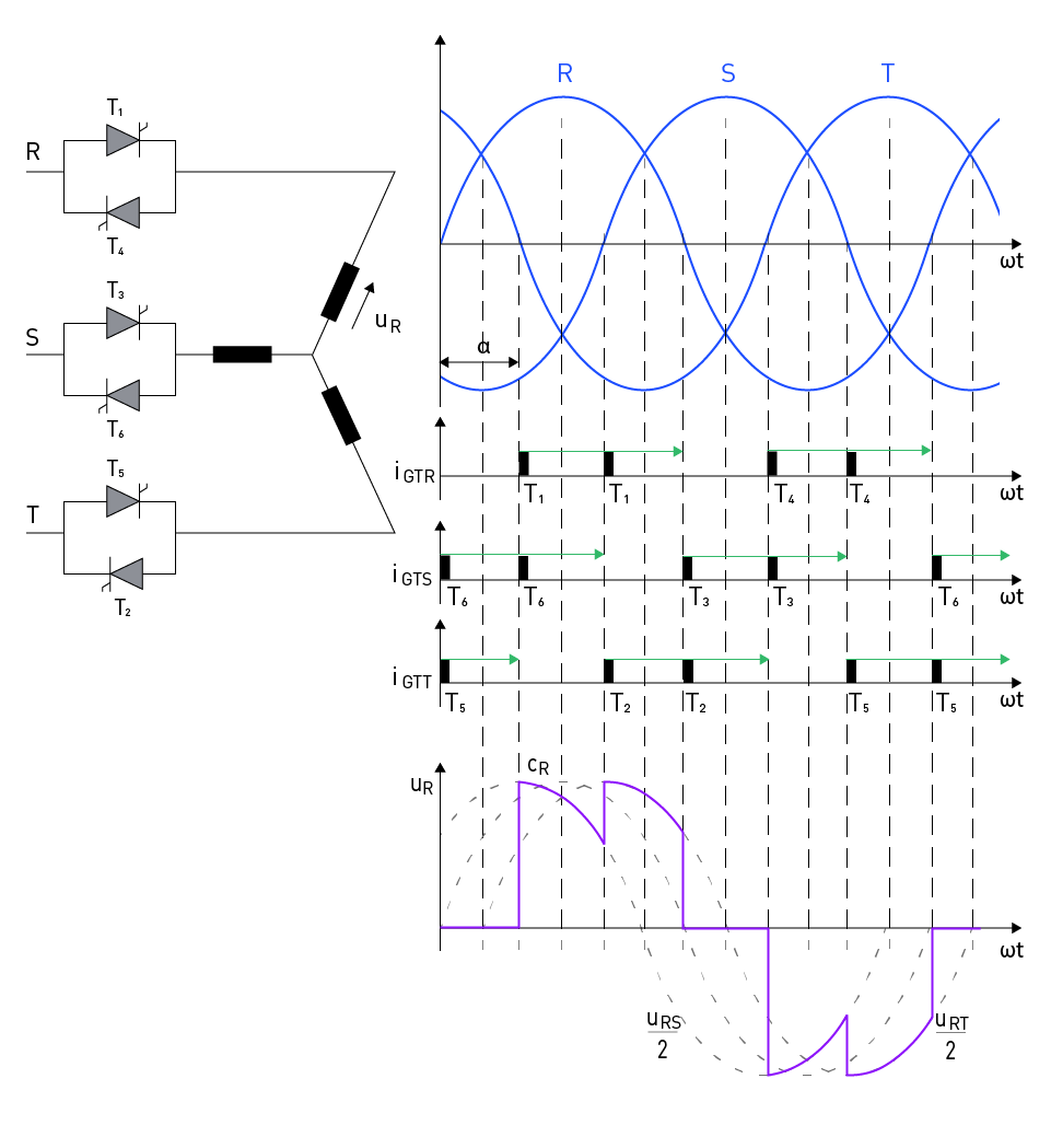
Various topologies of three-phase AC voltage controllers can provide three-phase loads with variable RMS AC voltage. The operation of the arrangement depicted on the left side of Figure 5 will be detailed in the following paragraphs. One of the distinguishing characteristics of this design is that it is not possible to make individual adjustments to the specific phase regulator currents. To determine the load current, at least two thyristors must be in operation simultaneously. If the firing pulses of the thyristors in each phase have the same sequence in relation to the voltages of the three-phase system generator (input voltage), then the regulator will work in a symmetrical manner. As a result, it is necessary for the firing pulses of thyristors T3 and T6 to lag after the firing pulses of thyristors T1 and T4 by an angle of 2π/3, respectively. Additionally, the firing pulses of thyristors T5 and T2 must lag behind the firing pulses of thyristors T1 and T4 by an angle of 4π/3. This requires shifting the firing pulses of thyristors in the same phase by an angle of π. This means that the thyristors must be activated in the order of T1, T2, T3, T4, T5, T6, T1, T2,... with a distance of π/3 between each pair. Furthermore, in order to fulfill the prerequisite of conducting a minimum of two thyristors, it is necessary for every thyristor to possess a confirmation pulse that is delayed by π/3 in addition to the firing pulse.
After the firing pulse sequence has been established, the next step is to ascertain the reference instant in relation to which the firing angle is measured. For a firing angle of α = θ degrees, the goal is to achieve the largest load current possible. This is due to the fact that the thyristors conduct as quickly as possible. When the load is directly connected to the input voltage, the maximum load current is achieved. Furthermore, when the resistive load is taken into consideration, the waveform of the current of independent loads is identical to that of the phase voltages of the three-phase system. Consequently, when the angle α = θ degrees, the point at which the phase voltage crosses through zero degrees is observed. An examination of the operation of this regulator will be carried out with the firing angle of 30 degrees as the characteristic. Figure 5 (right) shows the waveforms of the voltage on the load, also referred to as the load current.

Figure 5: Three-phase AC voltage controller
With a firing angle of α = 60 degrees, at the time ωt = α, thyristor T1 receives a firing impulse, while thyristor T6 receives a confirmation impulse. This causes both thyristors to conduct, and the load voltage becomes half of the line voltage uRS. During the time ωt = α + π/3, the thyristor T2 receives a firing impulse, which results in the conductivity of all three phases (T1, T2, and T6). Additionally, the load voltage is transformed into the phase voltage or eR.
At the same time, the phase voltage (eS) drops to zero and starts to reverse direction. This causes T6 to stop conducting, while only T1 and T2 continue to do so. As a result, the load voltage lowers to half of the line voltage, which is denoted by the symbol uRT. Thyristor T3 is engaged at the moment ωt = α + 2π/3, which results in the voltage eR reaching zero and reversing direction, thereby compelling T1 to cease conducting. When using this mode of operation, firing angles ranging from 60 degrees to 90 degrees are acceptable.
Types Of Loads And Their Effects
Three-phase alternating current voltage controllers can control a wide variety of loads. These loads include capacitive, inductive, and resistive loads. The type of load under control significantly influences the characteristics and performance of the voltage controller.
Resistive Loads: Loads that are entirely resistive have a current waveform that is identical to the voltage waveform and does not undergo a phase shift. The controller can maintain its basic function while minimizing the amount of harmonic distortion.
Inductive Loads: Motors and transformers are examples of inductive loads. These types of loads cause a phase shift between the waveforms of the voltage and the current, which in turn affects the firing angle and the conduction temperature. Because of this, one may experience increased harmonic distortion as well as a decrease in power factor, which necessitates further control and filtering methods.
Capacitive Loads: Capacitive loads have the potential to cause voltage and current waveforms to be out of phase, which can make control strategy more difficult to implement and may even result in voltage controller instability.
Control Strategies
It is possible to utilize a number of different control algorithms in three-phase AC voltage controllers in order to maximize power factor, eliminate harmonic distortion, and accomplish performance optimization. The following are examples of control methods that are frequently used:
Phase Angle Control: This method involves adjusting the firing angle of each thyristor to control the output voltage. Phase Angle Control is an example of this method. It is possible to make continual adjustments to the output voltage by delaying the firing angle, which results in a reduction in the effective output voltage.
Integral Cycle Control: Integral cycle control is a methodology that achieves discrete control of the output voltage. This method involves turning the thyristors on and off for a preset number of cycles. This technology is superior to phase angle control in terms of its ability to reduce harmonic distortion, making it the most suitable choice for applications that include low frequencies.
Hysteresis Control: This method effectively modifies the firing angle of the thyristors to maintain the RMS output voltage within a predetermined hysteresis band. This method improves dynamic responsiveness, but it may lead to an increase in harmonic distortion.
The specific requirements of the application, such as the type of load, the intended output voltage range, and the stability of the system, provide the basis for determining the appropriate control technique.
Three-Phase AC Choppers
Principle of Operation
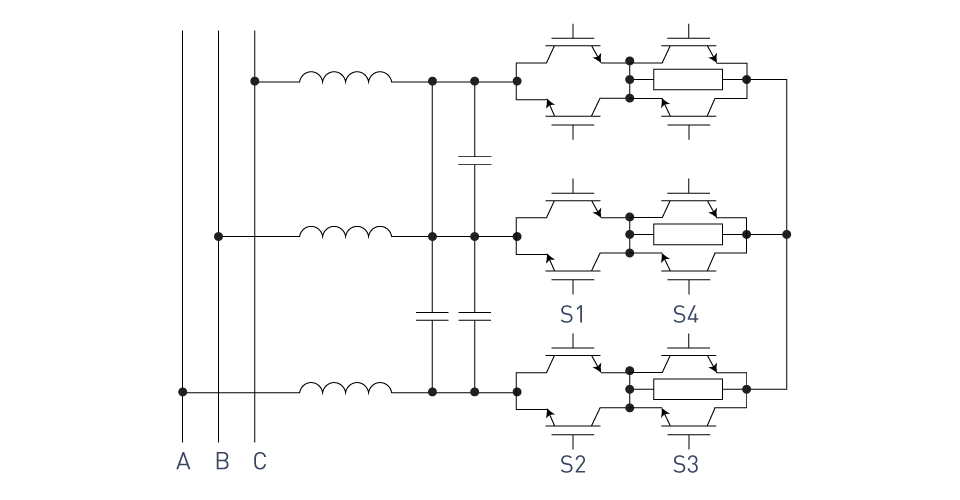
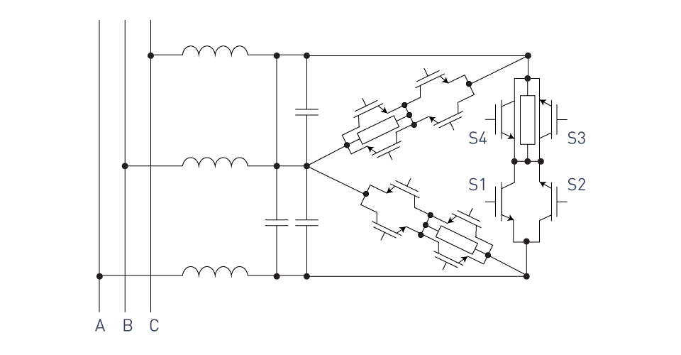
It is possible to manage the output voltage of a three-phase AC system by using power electronic devices known as three-phase AC choppers. These choppers work by chopping the input voltage waveform. In order to control the output voltage, these converters make use of high-speed semiconductor switches, such as IGBTs or MOSFETs, to interrupt the input voltage for a predetermined amount of time throughout each half-cycle. The pulse-width modulation (PWM) principle is the basis for the operation of a three-phase alternating current (AC) chopper. This principle entails changing the duty cycle of the switches to regulate the output voltage.
The following figures illustrate Three-phase AC choppers in wye or delta form.

Figure 6: Wye-connected three-phase AC chopper

Figure 7: Delta-connected three-phase AC chopper
Voltage Control Techniques
Three-phase alternating current helicopters can achieve optimal performance, reduced harmonic distortion, and improved power factor by utilizing a variety of voltage management strategies. Some of the most common methods for controlling voltage are listed below:
Sinusoidal PWM: This method is capable of generating pulse width modulation (PWM) pulses by comparing a sinusoidal reference signal and a triangular carrier signal. The amplitude and frequency of the reference signal influence the RMS output voltage and frequency, respectively. The reference signal determines these values.
Space Vector Modulation (SVM): Space Vector Modulation (SVM) is a complex method of voltage control that depicts three-phase voltages as a vector on a two-dimensional plane. SVM is also known as SVM. One method to properly regulate the output voltage is to adjust the location and magnitude of the vector.
Hysteresis Control: This method effectively modifies the duty cycle of the switches to maintain the output voltage within a predetermined hysteresis range. This method improves dynamic responsiveness, but it may lead to an increase in harmonic distortion.
Applications
Three-phase AC choppers find wide-ranging applications due to their high efficiency and rapid dynamic response in regulating the output voltage. Here are some of the most significant applications of three-phase AC choppers:
Motor Drives: Variable-speed motor drives, such as induction motor drives and synchronous motor drives, use three-phase AC choppers to modify the RMS output voltage and frequency in order to adjust the motor's speed and torque.
Power Factor Correction: Commercial and industrial settings can utilize three-phase AC choppers for power factor correction by adjusting the output voltage to match the input current. This allows for maximum efficiency in power factor correction.
Renewable Energy Systems: Three-phase AC choppers in wind energy systems can adjust output voltage and maintain acceptable power quality, especially when connected to the grid. This is especially relevant in the context of renewable energy systems.
Uninterruptible Power Supply (UPS): UPS systems can use three-phase alternating current (AC) choppers to correct the output voltage and protect sensitive loads from utility grid voltage fluctuations and interruptions.
Cycloconverters
Introduction to Cycloconverters
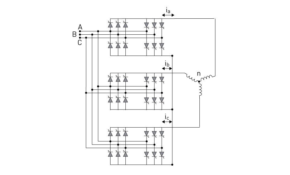
Through the utilization of cycloconverters, the RMS input AC voltage and frequency are directly converted to the RMS output AC voltage and frequency. This eliminates the need for an intermediary DC link to be present. Because of their exceptional frequency conversion capability, these converters are able to either reduce the frequency of the alternating current waveform that they receive as input or even produce a changeable output frequency. Cycloconverters are widely used in high-power applications that require smooth and continuous control of the output voltage and frequency. These applications are characterized by the need for conversion. Figure 8 is a representation of a bridge cycloconverter that converts three-phase to three-phase.

Figure 8: Three-phase to three-phase bridge cycloconverter
When compared to other topologies for AC/AC converters, cycloconverters offer a number of advantages. They can function at high power levels and have high efficiency because they do not contain any components that store energy, such as inductors and capacitors. Cycloconverters are also helpful for applications such as large motor drives, which require precise speed control because they are capable of producing a wide range of output frequencies, including very low frequencies.
There are, however, a number of important drawbacks associated with cycloconverters. These drawbacks include the requirement of a large number of switches, which increases complexity, and the generation of harmonics in the output waveform. In spite of these drawbacks, cycloconverters continue to be essential in a wide variety of high-power applications. These applications require precise control of the RMS output voltage and frequency, in addition to frequency conversion.
Principle of Operation
During operation, cycloconverters are able to generate the desired output alternating current waveform by selecting and regulating the appropriate input alternating current voltage segments. In order to accomplish this, power semiconductor switches, such as thyristors, are utilized. These switches have the ability to selectively connect or disconnect specific elements of the input waveform in order to generate the required output waveform.
There are two kinds of operations that a cycloconverter can perform: rectification and inversion. In the rectification mode, the cycloconverter processes the positive half-cycle of the input voltage to generate a positive output voltage. In contrast, the inversion mode generates a negative output voltage by passing over the input voltage's negative half-cycle. This leads to the generation of a positive output voltage. The cycloconverter can potentially generate a stepped output waveform with a frequency distinct from the fed waveform by appropriately adjusting the firing angles of the thyristors.
The sequence of triggering the thyristors selects the appropriate voltage segments from the input waveform to generate the required output waveform. It is the responsibility of the control circuitry to examine the waveforms of both the input and the output in order to ascertain the firing angles that are required in order to keep the RMS output voltage and frequency at the appropriate levels. Cutting-edge control techniques such as pulse-width modulation (PWM) or space vector modulation (SVM) can reduce the amount of harmonics present in the output waveform.
It is important to note that in order for cycloconverters to function, they do not require any components that provide the role of energy storage, such as inductors or capacitors. Consequently, this leads to a rise in efficiency as well as the capability to supervise larger power levels. On the other hand, the complexity of the control circuitry and the enormous number of power switches that are required could potentially increase the overall size and cost of the cycloconverter.
Types of Cycloconverters
Cycloconverters can be divided into four primary groups, each of which is determined by the configurations of their inputs and outputs. As some examples, here are some:
Single-Phase to Single-Phase Cycloconverters: These cycloconverters are capable of converting a single-phase alternating current input voltage into a single-phase alternating current output voltage with a different frequency. Single-phase to single-phase cycloconverters are most commonly employed for the purpose of controlling the speed of single-phase alternating current (AC) motors. These motors range from those found in home appliances to those in small industrial equipment.
Single-Phase to Three-Phase Cycloconverters: These cycloconverters take a single-phase alternating current input voltage and convert it into a three-phase alternating current output voltage with a completely new frequency. This type of cycloconverter typically drives three-phase induction motors or synchronous motors when only a single-phase supply is available. Compressors, fans, and small pumps are examples of typical applications.
Three-Phase to Single-Phase Cycloconverters: This type of cycloconverter takes an AC input voltage that is three-phase and converts it to an AC output voltage that is single-phase and has a different frequency. Despite their rarity, these cycloconverters can serve in situations where a three-phase source is required to power a single-phase load. For example, welding equipment or specialized power supplies are examples of situations where their use could be beneficial.
Three-Phase to Three-Phase Cycloconverters: Three-phase to three-phase cycloconverters, built specifically for this purpose, allow for the conversion of a three-phase alternating current input voltage to a three-phase alternating current output voltage with a different frequency. High-power industrial applications frequently use this type of converter to manage the speed of large induction motors in rolling mills, cement mills, or enormous pumps and compressors. Other examples include controlling the speed of synchronous motors. Because of their ability to manage high power levels and provide precise control of motor speed and torque, they are an enticing alternative for these demanding applications. Both of these capabilities make them an attractive choice.
Further classification of these cycloconverters can be accomplished by utilizing the waveforms of their outputs, which may include square wave, sinusoidal, or pulse width modulation (PWM) output. The application, power level, and desired output waveform quality level determine the type of cycloconverter used.
Control Strategies for Cycloconverters
It is essential to exercise control over cycloconverters in order to achieve the desired RMS output voltage and frequency, as well as to ensure the overall performance and efficiency of the system. Numerous control methods have been developed in order to regulate the operation of converters at various levels. The following are some of the most frequently implemented control strategies:
Phase-Controlled Strategy: The phase-controlled strategy is the control mechanism for cycloconverters that is considered to be the most fundamental and widely employed. Modulating the firing angles of the thyristors in each converter group is required in order to achieve the desired result of adjusting the RMS output voltage and frequency. In order to manage the firing angle, the intended output voltage and the waveform of the input voltage are both taken into consideration. The construction of this control technique is straightforward, and it also offers performance that is suitable for a wide variety of applications. On the other hand, it may result in harmonic distortion in the waveform of the output, which can lead to a decrease in both the efficiency and power quality of the system.
Pulse-Width Modulation (PWM) Control: When compared to phase-controlled approaches, pulse-width modulation (PWM) regulation provides superior control over the root-mean-square (RMS) output voltage and frequency, in addition to improved harmonic performance. Through the use of pulse width modulation (PWM) control, the output voltage may be controlled by adjusting the width of the output pulses. These pulses are generated by adjusting the firing angles of the thyristors. This strategy has the ability to improve power quality while simultaneously lowering the amount of harmonic distortion. However, it does call for more intricate control algorithms and more precise switching devices.
Vector Control: This is an additional advanced control solution for cycloconverters, particularly for three-phase systems. Vector control is a very useful technique. This method involves transforming the values of the three-phase alternating current into a two-dimensional vector representation. This makes it possible to manage the output voltage and frequency in a manner that is both simpler and more efficient. Vector control not only improves dynamic performance but also lessens the impact that harmonics have on the system's dynamic performance. Nevertheless, in comparison to other methods, it requires more complex control algorithms and a greater amount of processing resources.
Direct Torque Control (DTC): The term "Direct Torque Control" (DTC) refers to an effective method of control that places more of an emphasis on directly manipulating the torque and flux of the motor as opposed to regulating the RMS output voltage and frequency. Direct transistor control (DTC) has the potential to achieve faster and more precise control of the operation of the motor by directly altering these variables, which ultimately results in improved performance and efficiency. Applications that require quick and accurate torque control, such as robotics or electric cars, are excellent candidates for this control strategy because it is particularly effective. For DTC, on the other hand, it is necessary to have control algorithms that are more complicated and capabilities that allow for high-speed digital signal processing.
The specific application requirements, intended performance characteristics, and control system complexity establish the control strategy for a converter. Modern control approaches improve performance and efficiency, but they may necessitate more intricate and potentially expensive control gear and software.
Applications of Cycloconverters
Cycloconverters are highly versatile power electronic devices, found in a wide range of industries, due to their ability to convert alternating current (AC) voltage at one frequency to a different frequency. Especially useful in situations that need exact control of the output voltage and frequency, they are of great assistance. Generally speaking, cycloconverters are utilized for the following various purposes:
Motor Drives: Cycloconverters are commonly used in the control of electric motors, particularly large induction and synchronous motors. Motor drives are another common application. By precisely regulating the RMS output voltage and frequency, cycloconverters provide motor speed and torque control that is both smooth and efficient. Heavy industries like steel mills, mining, and cement plants, which utilize enormous motors for a variety of tasks, find them suitable for use.
Power Generation Systems: Cycloconverters are a type of device that can be utilized in power-generating systems for the purpose of regulating the frequency and root-mean-square voltage of the electricity that is generated. They are particularly helpful when using a prime mover with variable speed, like a gas or hydro turbine. The variable frequency output of the generator can be converted into a fixed frequency that is compatible with the power grid through the utilization of the cycloconverter in these particular conditions.
Renewable Energy Systems: Cycloconverters can also be utilized in renewable energy systems, such as wind turbines, in order to adjust the frequency and RMS voltage of the power that is created. This occurs in order to ensure that the electricity is produced efficiently. Through the process of converting the variable frequency output of renewable sources to the constant frequency that is required by the grid, they make it possible for these sources to be incorporated into the electrical grid.
Traction Systems: Cycloconverters are an essential component of electric traction systems, including electric trains and trams, among other types of electric transportation. They make it possible to precisely manage the speed and torque of the traction motor, which in turn makes it possible to accelerate and decelerate in an effective and smooth manner. This not only improves the comfort of the passengers but also boosts the performance of the traction system and the energy economy of the vehicle.
Marine Propulsion Systems: Cycloconverters are utilized in large marine propulsion systems, such as those found in ships and submarines, in order to manage the speed and torque of the propulsion motors. These cycloconverters contribute to the optimization of the performance and efficiency of the propulsion system, which ultimately results in reduced emissions and saves on fuel. Specifically, they achieve this by providing precise control over the motor's operation.
High-Power Variable-Frequency Drives (VFDs): Cycloconverters are a viable choice for high-power variable-frequency drives (VFDs) applications that require direct frequency conversion. These applications are common in the field of variable-frequency drives. When compared to traditional variable frequency drives (VFDs), which convert frequencies through the use of rectifiers and inverters, these VFDs offer an alternative that is more energy-efficient.


直接登录
创建新帐号