Introduction to Single-Phase AC/AC Converters
For the purpose of regulating the root mean square (RMS) and/or phase of the voltage or current in single-phase alternating current (AC) systems, power electronic equipment such as single-phase AC/AC converters are utilized. All of these converters have the ability to change the RMS voltage, frequency, or phase angle of the AC waveform, which enables them to provide precise control and improved performance in a wide range of applications. Single-phase alternating current (AC) power systems are the most prevalent type of electrical supply in residential, commercial, and light industrial contexts. They are widely used in these types of power transmission networks.
The classification process divides single-phase AC/AC converters into two distinct types based on the operating principles they employ:
- Phase-controlled AC voltage controllers
- Single-phase AC choppers
The following sections will demonstrate that each category has unique characteristics, control mechanisms, and specific applications. Within the scope of this chapter, we will discuss the fundamental concepts, guiding principles, and control strategies that are associated with single-phase AC/AC converters. A discussion of how the performance of these converters is affected by different loads will also be included, as well as an overview of how these converters are utilized in a variety of power electronics systems. By having a fundamental understanding of the fundamental concepts and procedures of single-phase AC/AC converters, engineers and students are able to construct and optimize power electronics systems for a wide range of applications, including but not limited to motor speed control, lighting systems, and more.
Phase-Controlled AC Voltage Controllers
Principle of Operation
Power electronic switches, such as thyristors (also known as silicon-controlled rectifiers or SCRs), or triacs, are utilized by a category of single-phase AC/AC converters known as phase-controlled AC voltage controllers. These controllers are also referred to as phase-controlled regulators or thyristor-based AC controllers. The purpose of these controllers is to regulate the conduction angle or firing angle of these switches in order to control the RMS output voltage. The conduction angle, which is represented by the equation, is the amount of time that passes between the thyristor being activated and current being able to flow through the load. By adjusting the firing angle, one can accurately adjust the output voltage to the desired level, thereby gaining control over the AC waveform configuration.
A standard phase-controlled AC voltage controller links its thyristors in an antiparallel form, also known as an inverse-parallel design. By doing so, the controller is able to manage current flow in both directions and regulate both the positive and negative half-cycles of the AC waveform that is being input. A control circuit, which often makes use of a microcontroller or a digital signal processor (DSP), is responsible for producing the gating signals that are required to turn on the thyristors at the appropriate firing angle.
Types of Loads and Their Effects
The type of load that connects to the converter can affect the performance of phase-controlled alternating current voltage controllers. There are many different types of loads, but some examples include capacitive, inductive, and resistive loads.
1. Resistive Loads
In situations where the loads are totally resistive, the waveform of the current follows the waveform of the voltage, and the phase angle between the voltage and the current stays the same. In this particular circumstance, a phase-controlled AC voltage controller is able to provide output voltage control that is both smooth and continuous, with extremely low distortion.
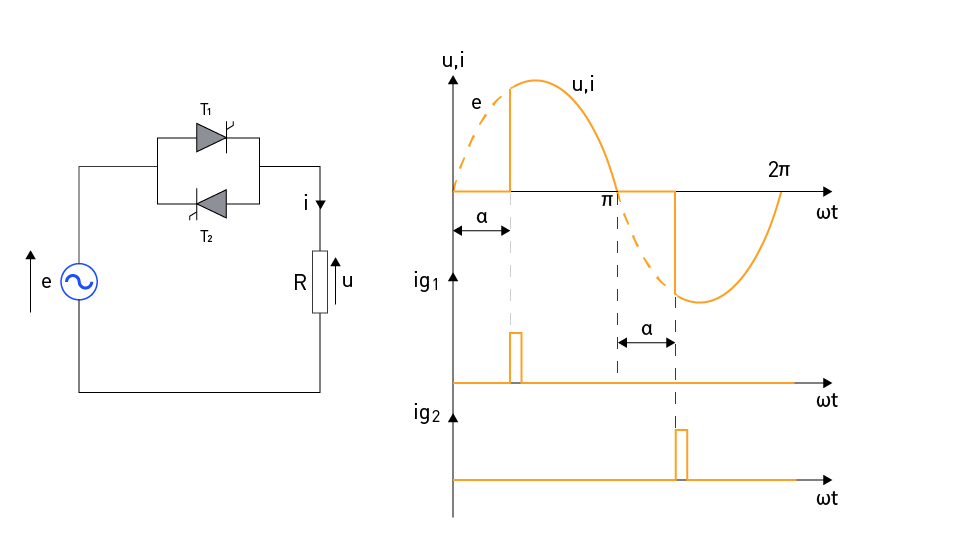
A single-phase AC voltage controller that contains thyristors is coupled in an antiparallel manner, as shown in Figure 1 (left). This particular configuration is frequently utilized due to the fact that it requires a smaller number of switching elements, which ultimately leads to the lowest possible losses. It is necessary to obtain galvanic isolation of the control circuit in this design because the thyristor cathodes have a variety of potentials. The fact that the load is only intermittently linked to the input voltage throughout the course of a half-cycle is the starting point for the concept that underpins the idea of managing the output RMS voltage. The length of time that this section of the half-cycle continues to exist is determined by the instant that the thyristor is activated (by means of the application of a firing pulse).
This particular instant is defined by the firing angle α, which is the duration of time that elapses between the point at which the thyristor begins to become forward-biased and the point at which it receives a firing pulse.
There is a depiction of the waveforms for the input voltage, the firing pulse, and the output voltage (or current) in Figure 1 (right). Thyristor T1 experiences a forward bias during the positive half-cycle of the input voltage. The thyristor T1 becomes reverse-biased when the load current is reduced to zero and the input voltage is shown to be shifting in the opposite direction. During the time ωt = α, the ig1 pulse is responsible for activating this thyristor, which then continues to conduct until the end of the half-cycle. For the duration of the subsequent half-cycle, thyristor T1 will be in reverse bias. This is a significant amount of time longer than the amount of time that is required for it to turn off. When the thyristor T1 is conducting, the voltage that is measured across the load is the same as the voltage that is being input. During the negative half-cycle of the input voltage, events that are comparable to those described above take place, with the exception that thyristor T2 conducts since it is thus negatively biased.

Figure 1: Single-phase full wave AC voltage controller with resistive (R) load
By adjusting the firing angle of the thyristor, which can range from α = π to α = 0, it is possible to vary the RMS value of the output (load) voltage from zero to the RMS value of the input voltage. The RMS value of the output voltage for the firing angle is as follows:
$$U = \sqrt{\frac{1}{\pi} \int_{\alpha}^{\pi} \left( \sqrt{2} E \sin(\omega t) \right)^2 \, d(\omega t)}$$By altering the equation ωt = x:
$$U = E \cdot \sqrt{\frac{2}{\pi} \int_{\alpha}^{\pi} \frac{1 - \cos(2x)}{2} \, dx}$$ $$⇔U = E \cdot \sqrt{\frac{2}{\pi} \left( \frac{\pi - \alpha}{2} - \frac{1}{4} \left( \sin(2\pi) - \sin(2\alpha) \right) \right)}$$ $$⇔U = E \cdot \sqrt{1 - \frac{\alpha}{\pi} + \frac{\sin(2\alpha)}{2\pi}}$$in which [Equation] represents the root-mean-square value of the input voltage and U represents the value of the output voltage at its RMS.
2. Inductive Loads
Connecting an inductive load to the converter causes the phase shift that results from the current trailing behind the voltage. Examples of such loads are a transformer and an induction motor. This results in an increase in harmonic distortion and a decrease in power factor. To mitigate these consequences, it may be necessary to take certain additional measures, such as controlling the current through the inductor.
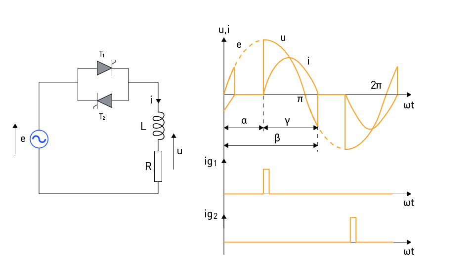
Figure 2 (left) illustrates a single-phase AC voltage controller with a load that is represented by an inductor with an inductance of L linked in series with a resistor with a resistance of R. Figure 2 (right) displays the waveforms of the input voltage, output voltage, and current, along with the trigger pulses used to activate the thyristor at the firing angle. These waveforms are depicted in the figure.

Figure 2: Single-phase AC voltage controller with LR load
As soon as the trigger pulse is applied to thyristor T1 at the time ωt = α, T1 begins to conduct, and the load voltage is the same as the input voltage. Thyristor T2 becomes reverse-biased as a result of the voltage drop that occurs in thyristor T1 while it is conducting conductivity. This occurs when thyristor T1 stops conducting. When thyristor T1 stops conducting at moment at ωt = β, the thyristor T2 becomes forward-biased by input voltage, which at that moment has a value of:
It is required to install sufficient RC protection in parallel with the thyristors, as the sudden surge in the forward-biasing voltage triggers the thyristor without the user's consent.
The thyristors' conduction angle can be defined using the following expression:
$$\gamma = \beta - \alpha$$When conducting the thyristor, two distinct time intervals occur. The first interval, which spans from ωt = α to ωt = π, is characterized by the fact that the input (grid) voltage and the output (load) current are in the same direction. This indicates that energy is extracted from the grid and transported to the load. The resistive portion of the load, on the other hand, is responsible for the consumption of a portion of that energy, while the remaining portion is stored in the inductor as magnetic energy.
During the second interval, which spans from ωt = π to ωt = β, the grid voltage and the load current exhibit divergent directions. This indicates that the magnetic energy generated by the inductor is partially returned to the grid and partially consumed by the resistive portion of the load. After the inductor has used up all of its magnetic energy, the current will drop to zero, and the thyristor will no longer conduct electricity. The firing angle of the thyristor decreases, resulting in an increase in the amount of energy stored in the inductor. Additionally, the amount of time required to burn that energy grows, resulting in an increase in the angle β. If the angle β is equal to π + α, then the conduction angle of the thyristor is equal to π. This signifies the absence of any interruptions in the load current, making it equivalent to a direct connection to the grid voltage.
3. Capacitive Loads
The current flows in the opposite direction of the voltage when capacitive loads, such as capacitive filters, are present. This leads to an increase in harmonic distortion and reduced power factor. It is possible to overcome these concerns by utilizing compensation schemes.
Control Strategies
Depending on the specific requirements of a particular application, a variety of control schemes are available for optimizing the performance of phase-controlled AC voltage controllers. These are some examples of common control strategies:
On-off control: This method activates the thyristor at a predetermined firing angle and switches it off when the voltage waveform reaches zero. This method is straightforward, but it has the potential to lead to significant voltage swings and inadequate load management.
Phase angle control: Within the context of fluctuating load conditions, phase angle control is a technique that involves making continuous adjustments to the firing angle in order to keep the RMS output voltage constant. When contrasted with the on-off control method, this strategy offers improved load management and fewer voltage swings.
Integral cycle control: Phase-controlled AC voltage controllers can meet the specific requirements of a wide variety of applications by selecting an appropriate control mechanism. These applications include motor speed control, lighting systems, and even larger ones.
Single-Phase AC Choppers
Principle of Operation
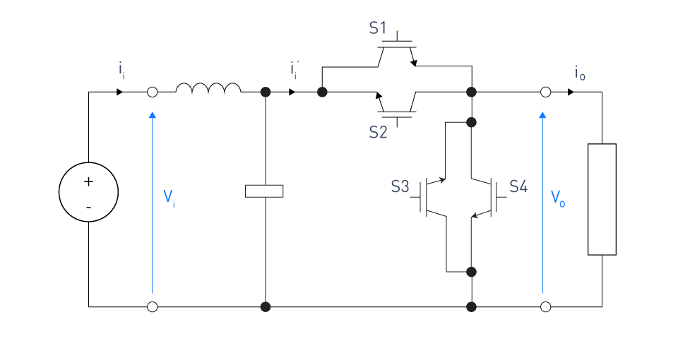
Single-phase AC choppers, a type of AC/AC converter, use power electronic switches to modify the output voltage waveform without altering the input frequency. To split the input waveform into smaller pieces, these converters use fast-switching parts like MOSFETs or IGBTs. This enables precise control over the output voltage.

Figure 3: Single-phase PWM AC chopper circuit with input filter

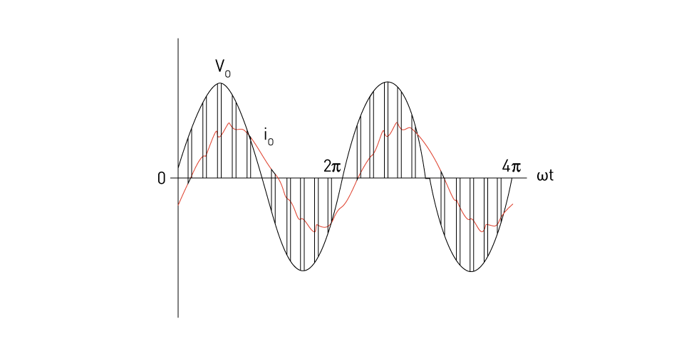
Figure 4: Output waveforms of a single-phase PWM AC chopper.
Voltage Control Techniques
Voltage control methods are critical in order to effectively manage the output voltage of single-phase AC choppers. AC helicopters most frequently utilize pulse width modulation (PWM) as their control method. In order to control the RMS output voltage, pulse width modulation (PWM) control requires making adjustments to the duty cycle, which signifies the proportion of on-time to the overall duration of a switching period. The pulse width modulation (PWM) method offers superior voltage control and lower harmonic distortion in comparison to the phase angle control method. Other approaches for controlling voltage, such as hysteresis control and frequency control, may also be applied, depending on the requirements of the application.
Applications
Power electronics utilizes single-phase alternating current choppers for their versatility in delivering precise voltage regulation and rapid dynamic response. The following are some examples of typical applications:
Lighting systems: AC choppers are used in dimming control systems for incandescent lamps and light-emitting diodes (LEDs), which are used in situations where precise voltage regulation is necessary for the purpose of managing the degree of brightness.
Motor speed control: The use of single-phase alternating current choppers in motor speed control applications allows for the voltage that is supplied to the motor to be adjusted, which in turn allows for the speed of the motor to be managed. This is especially advantageous in applications involving fans, pumps, and conveyors.
Power supplies: Electronic devices can use AC choppers to maintain a stable RMS output voltage, irrespective of the input voltage or load conditions. This ensures that the electrical equipment functions in a reliable and consistent manner at all times.
Heating systems: AC choppers are employed in heating systems to manage the voltage given to the heating element, which in turn controls the temperature. It is beneficial in applications such as furnaces used in industrial settings and heating systems used in residential settings.


直接登录
创建新帐号