AN142 - Linearity in side-shaft configuration: what should one care about?

Get valuable resources straight to your inbox - sent out once per month
We value your privacy
1. Preamble
When using MagAlpha in side-shaft configuration, the user needs to consider a couple of criteria to achieve a highly linear output. The MagAlpha angle sensor has a built-in linearization option (called “BCT”) to handle the fact that the 2 orthogonal components of the magnetic field seen by the sensor have different amplitudes as the magnet makes a revolution. However, it turns out that some imperfections in the sensor or magnet position, or in the way that the magnet is magnetized, can generate errors that cannot be compensated by BCT adjustment. The present note describes which features need to be watched and how much linearity one can expect knowing the imperfections. It can help to specify mechanical and magnet tolerances.
1.1 Ideal situation
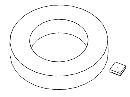
The magnetic field produced by a finite cylinder with uniform magnetization along a circular trajectory (see Figure 1) centered on the magnet are sinusoidal functions of the angle.
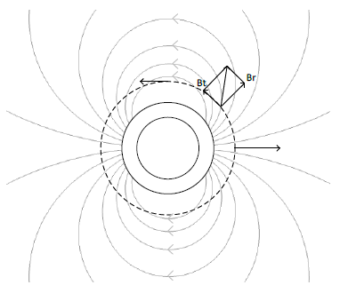
Figure 1 Magnetic field lines outside a uniformly magnetized ring
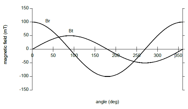
Figure 2 Radial and tangential components of the magnetic field along a circular trajectory around the ring
For a ring of finite height, the amplitudes of Br and Bt are in general not the same: $k \equiv Br / Bt \neq 1.$ Analytical expressions for Br and Bt can be found for instance here [Caciagli et al. Journal of Magnetism and Magnetic Materials 456 (2018) 423-432]. The different amplitudes results in a non-linear sensor output (the so-called "elliptic" error). The error curve essentially has a second harmonic component (it makes two sinewaves for one full rotation). This error can easily be corrected by changing the ratio between the radial and tangential sensitivity. In the MagAlpha this ratio is controlled by the parameter "BCT". More details about the BCT adjustment can be found in any MagAlpha datasheet.
By side-shaft, we mean any configuration where the sensor is away from the axis of rotation. The 3 kinds of side-shaft configurations are shown in Figure 3.

Figure 3 Different side-shaft configurations: Left: side-ring, center: ortho, right: top-ring
1.2 Real situation
In real systems some imperfections create nonlinearities which cannot be compensated by any BCT adjustment:
- Positional imperfections: non-ideal magnet and sensor position due to the system mechanical tolerances
- Magnetic imperfections: non-ideal magnetization of the magnet
If the resulting error curve has a different order than second harmonic, the BCT setting can obviously not compensate the error. Even if the error is a second harmonic, if the phase is different than the error curve resulting from k ratio different than 1, the error cannot be compensated by BCT setting. And even if the error can be compensated by a BCT adjustment, this error is usually not identical from magnet to magnet, therefore it requires individual calibration at production.
2 Positional imperfections
2.1 Sensor rotation around its axis
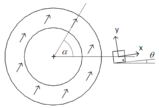
Figure 4 Imperfect sensor orientation: $\theta$ is the rotation angle around the sensor normal axis
Assume that the sensor is perfectly aligned and the BCT parameter is perfectly set to compensate the magnetic field k ratio. If the sensor rotates along its normal direction, the output becomes non-linear:
$$err = − \frac \theta2 \left(k +\frac1 k + (k − \frac 1 k) cos 2\alpha\right)$$Where $\alpha$ is the shaft angle. It means that the error is larger with a larger k ratio. Note that if both radial and tangential components are equals (k = 1), the output is only offset by an angle $\theta$ and remains perfectly linear.
Just like the field elliptic error, the error resulting from a sensor rotation has mainly a second harmonic component. Yet, compared with the elliptic error, this error is shifted by 45 degrees. It means that this error cannot be compensated by BCT trimming. This is expected because the BCT parameter acts on the ratio of sensitivity to the x field compared to the y field, and in case of sensor rotation the x and y components of the sensor are not aligned with the magnet radial and tangential components.
Note: this formula above is valid for any configuration: side-ring, ortho or top-ring.
2.2 Magnet eccentricity
Magnet eccentricity produces a first harmonic error of amplitude (in deg) $\frac {2e} r \frac {180} \pi$ Where $e$ is the eccentricity (Figure 5). This expression is exact in 2D. For a finite magnet height, there is a small additional 3rd harmonic component.
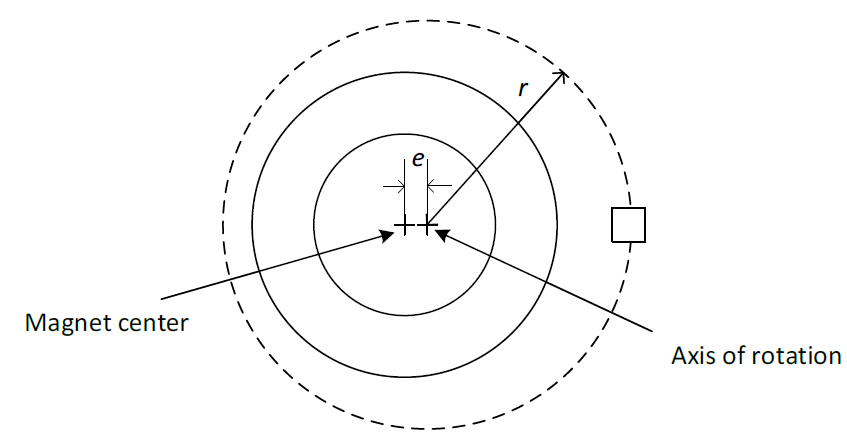
Figure 5 Eccentricity of the ring: the center is shifted by the distance $e$
The $\frac {2e} r \frac {180} \pi$ amplitude is valid for side-ring. It can be used to get a rough idea of the errors in ortho or topring configuration, but in top-ring, the effect is much larger because an eccentricity creates an important variation of the $k$ ratio during one revolution.
2.3 Radial or axial displacement
Assume the BCT is perfectly set for a particular sensor position. If a displacement modifies the $k$ ratio by the quantity $\Delta k$, the resulting error is a second harmonic curve:
$$atan ( (1 + \Delta k) tan\ \alpha) \approx \alpha + \frac {\Delta k} 2 sin\ 2\alpha$$This error is especially severe for displacement along large gradient of $k$. Examples of large $k$ gradient regions are shown in Figure 6
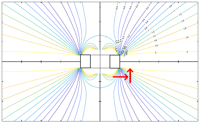
Figure 6 Lines of equal $k$ values for a typical magnet ring. large $k$ gradients are shown by red arrows
As a consequence, the critical sensor displacements are:
- The radial displacement for top-ring
- The axial displacement for ortho
The side-ring configuration is less affected. See Figure 7.

Figure 7 Axial and radial displacements. In red the critical displacements.
3. Errors due to magnet imperfections
These imperfections occur during the fabrication process, in particular during the magnetizing step.
3.1 Non-uniformity due to the demagnetization field
This distortion applies in general to all magnet rings. It is more severe with narrow walls (i.e. inner diameter close to output diameter). Qualitatively, instead of being parallel, the magnetization vector tends to follow the ring curvature. See Figure 8.
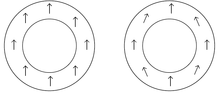
Figure 8 Left: ideal homogeneous magnetization. Right: typical magnetization in real magnets
To be magnetized in its final state, the ring is immerged in a uniform strong field oriented along its diameter. What matters for this step is the total magnetic field felt by a local grain of material. This field, usually called H, is the sum of the applied field (far for the cylinder) and the “demagnetization field” i.e. the field produced by the neighbor grains of the cylinder itself. It turns out that for a closed and high cylinder, H is uniform inside. As a consequence, all of the magnetic domains get oriented along the same direction. Uniform cylinders generate perfectly sinusoidal radial, tangential and axial fields along an external circular trajectory. This behaviour does not hold true for a ring (hollow cylinder): the H field will deviate as in Figure 9. This is not a default of the magnet but a consequence of its shape.
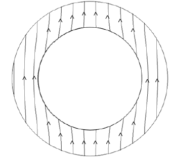
Figure 9 Total field H inside a ring, resulting from the application of a uniform field $H_{ext}$
In general, this effect makes the radial (or axial) field more triangular and the tangential field more “square”. See a typical distortion in Figure 10.
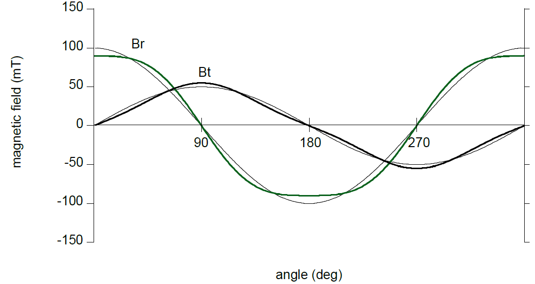
Figure 10 Third harmonic distortion of the radial and tangential field components
It takes the form of a third harmonic distortion:
$$B_r(\alpha) = B_r^0(cos\ \alpha - D\ cos\ 3\alpha)$$ $$B_t(\alpha) = B_t^0(sin\ \alpha - D\ sin\ 3\alpha)$$Where $D$ is the distortion ratio (that we assume to be the same for both components). When $D$ is small it results in an error:
$$err = (-D + D^2) sin\ 2\alpha - \frac {D^2} 2 sin\ 4\alpha + ..$$It essentially means an error with a second harmonic of amplitude $D + D^2 -$ and a $4^{th}$ harmonic of amplitude $\frac {D^2} 2$. In principle, the second harmonic error has the same phase as the elliptic error, therefore it can be compensated by BCT trimming.
3.2 Non-uniformity due to imperfect applied field
Difference error can result from imperfect positioning of the piece inside the magnetization device (or for anisotropic magnets during the pressing). Due to its finite size, the H field lines are not perfectly parallel. If the piece is off-centered, the curvature of the field lines is asymmetric, resulting in a first harmonic error. This affects the sensor reading in any side-shaft configuration.

Figure 11 Left: ideal magnetization. Right: non-uniformity due to imperfect centering in the magnetization device. $\beta$ is the purely radial field angle shift.
One way to measure this asymmetry is to record the radial or tangential field and look for asymmetry between one half turn and the other one. See Figure 12. The resulting sensor error is a first harmonic error of amplitude $\beta$.

Figure 12 Radial and tangential field measured around an imperfectly magnetized ring
3.3 Magnetization tilt
The magnetization of commercial magnet rings or cylinders is usually not strictly planar (i.e. perpendicularto the rotation axis). Instead the magnetization vector can be tilted in the axial direction by a couple of degrees ($\pm 5$ degrees is a common tolerance). See Figure 13.

Figure 13 Magnetization tilt
The magnetization can be seen as a superposition of the ideal magnetic field with a purely axial perturbation field. See Figure 14. In side-ring configuration the magnetic field produced by the "axial magnet" is perpendicular to the die plane, i.e. not measured (Figure 14). Therefore magnetization tilt does not affect the reading of side-ring sensors. This is not the case for the ortho or top-ring configurations.

Figure 14 Top: the tilt can be decomposed into an ideal diametrical magnetization and an axial perturbation. Bottom: the axial perturbation affects the ortho and top-ring configurations.
We can roughly approximate the effect of the tilt on the ortho configuration. The axial ring creates a constant field at the sensor position, regardless of the shaft angle. The worst error occurs when the field of the ideal magnet is purely tangential at the sensor location: in this situation the parasitic field is perpendicular to the ideal field:
$$error = atan \left(\frac {B_{axial}}{B_t}\right)$$In the limit where the sensor is close to the magnet mid-height and the magnet height is small, this error can be approximated by:
$$error = atan \left(\frac1 2 tan\ \theta_m \right)$$Where $\theta_m$ is the magnetization tilt.
As it can be qualitatively observed from Figure 14 a significantly larger error will affect the top-ring configuration.
4. Summary
| Cause | Relevant Parameter | H1 | H2 | H4 | Applies to | Can be BCT compensated | ||
| Side ring | Top ring | Ortho | ||||||
| Sensor rotation | $k$:ellipticity ratio $\theta$: sensor rotation | 0 | $$atan \left(\frac 1 2 tan\ \theta_m \right)$$ | 0 | yes | yes | yes | No |
| Magnet eccentricity | $\frac e r$: eccentricity to sensor radius ratio | $$\frac {2e} r$$ | 0 | yes | yes | yes | No | |
| Sensor radial or axial displacement | $\Delta k$:ellipticity ratio change | 0 | $$\frac {\Delta k}2$$ | 0 | yes | yes | Yes | |
| Demagnetization distortion | $D:3^{rd}$ harmonic distortion ratio | 0 | $$D - D^2$$ | $$\frac {D^2} 2$$ | yes | yes | yes |
H2 yes - H4 no |
| Non uniform magnetization field | $\beta$ shift of the Br maximum | $$\beta$$ | 0 | 0 | yes | yes | yes | No |
| Magnetization tilt | $\theta m$: the tilt | $$atan \left(\frac 1 2 tan\ \theta_m \right)$$ | 0 | 0 | yes | yes | No | |
Note: multiply by $\frac {180}\pi$ to obtain the amplitudes in deg.


直接登录
创建新帐号