Flyback Converters
Flyback converters are an essential type of isolated power supply commonly found in gate driver circuits. They are particularly well-suited for applications that prioritize compact size, efficiency, and reliable isolation at lower to moderate power levels. Known for their simplicity and versatility, flyback converters operate by storing energy in a magnetic field during one phase and transferring it to the output during another phase. This allows for electrical isolation and power conversion.
Fundamental Operation and Structure
A flyback converter consists of a transformer, a switch (typically a MOSFET or IGBT), a diode, and output capacitors. Energy is stored in the primary winding of the transformer during the switch's "on" phase. When the switch is in the "off" position, the energy that was stored is transferred to the secondary winding and subsequently to the load via the diode, resulting in an isolated DC output. This operation allows the converter to effectively control energy transfer across the isolation barrier, which is essential for gate-driving applications.
Advantages in Gate Driver Applications
Efficiency and Compactness: Flyback converters are known for their exceptional efficiency, making them an ideal choice for gate drivers where power efficiency is of utmost importance. Their small size allows for easy integration into crowded PCB layouts commonly found in gate driver applications, aiding efforts to make things smaller.
Flexibility: These converters have the ability to provide multiple isolated outputs from a single transformer, making it easier to power various gate drivers or auxiliary circuits. This simplifies the overall power supply design and adds flexibility to the system.
Cost-Effectiveness: The straightforward design and minimal number of components in flyback converters make them a budget-friendly option for fulfilling isolated power supply requirements in gate drivers.
Design Considerations and Challenges
Transformer Design: To ensure optimal performance of the flyback converter, it is crucial to meticulously design the transformer to effectively handle the necessary power level and ensure sufficient isolation. These factors need to be taken into account: core material, winding ratios, and insulation.
Electromagnetic Interference (EMI): EMI can be a concern when it comes to flyback converters, as they have a tendency to generate significant electromagnetic interference as a result of their switching action. Attention to detail, effective shielding, and thorough filtering are essential to minimize electromagnetic interference and meet regulatory requirements.
Thermal Management: The efficiency of flyback converters can fluctuate based on load and input voltage, which can impact their overall performance. Designers need to carefully handle the thermal aspects, particularly in compact gate driver applications where thermal dissipation can be quite challenging.
Forward Converters
The reliability and efficiency of forward converters, a type of isolated power supply, make them highly valued in moderate- to high-power applications. They are particularly useful for powering gate drivers. With direct energy transfer from input to output during the conduction phase of the switching element, forward converters provide a simple way to achieve electrical isolation and voltage conversion.

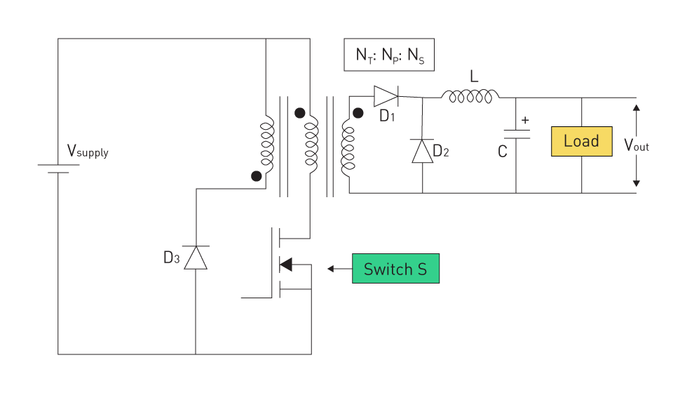
Figure 1: Forward Converter
Fundamental Operation and Structure
The design of the forward converter involves several components, such as a transformer, switching transistor, diodes, capacitor, and inductor. In a forward converter, the energy transfer takes place directly through the transformer during the switch's on-time, unlike in flyback converters. This seamless transfer enables a steady stream of energy to reach the load, resulting in enhanced efficiency and decreased strain on the switching components. One notable feature of forward converters is the implementation of a demagnetizing winding or an active clamp circuit. This feature serves to reset the core of the transformer, promoting steady performance and safeguarding against saturation.
Advantages in Gate Driver Applications
High Efficiency: Forward converters excel in power efficiency, especially at higher power levels. This makes them an ideal choice for gate driver circuits in various applications, including electric vehicles, industrial drives, and renewable energy systems, where maximizing power efficiency is crucial.
Good Transient Response: These converters excel at providing a rapid response to changes in load conditions, making them ideal for gate driver applications.
Stable Operation: The reset mechanism in forward converters guarantees stable operation, even when faced with varying input voltages and load conditions. This greatly enhances the dependability of gate driver circuits.
Design Considerations and Challenges
Complexity in Transformer Design: The inclusion of reset mechanisms in transformer design for forward converters introduces additional complexity. To achieve peak performance, the transformer and reset circuit must be meticulously designed to effectively handle the anticipated power levels and guarantee smooth operation.
Thermal Management: Properly managing the heat generated by the switching elements and the transformer is of utmost importance in forward converter designs. Efficient thermal management solutions are crucial for ensuring optimal performance and increasing the longevity of the converter.
Size and Cost: Although forward converters provide excellent efficiency and reliable performance, their design intricacy and the need for extra components may lead to increased size and cost when compared to more straightforward isolated power supply options. Designers need to carefully consider these factors in relation to the application requirements.
Push-Pull Converters
Push-pull converters are a commonly used architecture in isolated power supplies. They are known for their high efficiency and ability to deliver more power, making them a great option for gate driver applications that require a lot of power in a small space. This configuration utilizes a duo of transistors that take turns directing current through a transformer, resulting in effective power conversion and electrical isolation at the same time.
Fundamental Operation and Structure
The key aspect of a push-pull converter is its utilization of two switches, usually transistors, that function in opposite phases. To ensure a safe operation, a dead time is incorporated in the middle to prevent any potential short circuit in the primary winding. The "on" state of a transistor transfers energy from the input to the transformer's primary winding, pushing it forward. Conversely, the activation of the second transistor draws energy through a distinct section of the primary winding. The back-and-forth movement of this mechanism ensures a smooth and consistent flow of energy to the second coil and, consequently, to the final output. The rectifier diodes and bypass capacitors efficiently convert the input to a stable DC output, making them perfect for powering gate circuits.
Advantages in Gate Driver Applications
Higher Power Capability: Push-pull converters are highly efficient in handling higher power levels, making them a suitable choice for power-intensive applications such as gate drivers.
Improved Efficiency: The push-pull design reduces component voltage stress, allowing for a more efficient magnetic design for the transformer. Efficiency plays a crucial role in minimizing heat generation and improving the reliability of gate drivers.
Reduced Electromagnetic Interference (EMI): EMI reduction is achieved through the symmetrical operation of the push-pull topology, which helps to cancel out electromagnetic emissions generated during the switching process.
Design Considerations and Challenges
Transformer Design: The design of the transformer plays a crucial role in determining the performance and efficiency of a push-pull converter. Design plays a critical role in ensuring efficient energy transfer and maintaining proper isolation between the input and output.
Switching Strategy: Precision in controlling and timing the switching elements is crucial to avoid transformer saturation and maintain balanced operation. This necessitates advanced control circuits that can effectively handle the switching that occurs out of phase.
Thermal Management: Despite their efficiency, push-pull converters can generate significant heat at high power levels. Efficient thermal management strategies are crucial for ensuring optimal performance and extending the lifespan of the gate driver and its power supply.
Complexity and Cost: The push-pull topology can be more intricate compared to certain single-switch designs, which may result in a greater number of components and a higher overall cost. Nevertheless, the advantages of enhanced power capability, efficiency, and reduced emissions frequently outweigh the increased intricacy in challenging scenarios.
LLC Converters
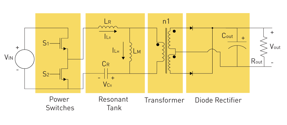
Among the many types of isolated power supply, LLC resonant converters are a particularly sophisticated category. They are distinguished by their exceptional efficiency and power density. In the realm of gate driver applications, this architecture has become increasingly popular, particularly in situations where precise control, efficiency, and a broad input voltage range are of fundamental importance. Power switches, a resonant tank, a transformer, and a diode rectifier are the four components that comprise an LLC converter.

Figure 2: LLC Converter
Fundamental Concepts and Operation
The most crucial part of an LLC converter is the resonant tank circuit, which consists of two inductors and one capacitor. This configuration generates a resonant frequency, enabling the converter to switch at or near this frequency. This significantly reduces the amount of energy lost during the power switch's transition stages. Through its operation in resonance, the LLC converter is able to achieve a high level of power conversion efficiency, which is especially helpful for the harsh conditions of gate driver circuits.
Advantages for Gate Driver Applications
High Efficiency Across Wide Load Range: LLC converters maintain high efficiency over a broad load range, making them suitable for gate driver applications with variable power demands.
Excellent EMI Performance: LLC converters are suitable for gate driver applications with fluctuating power demands because they maintain a high level of efficiency across a wide load range. This makes them suitable for use in gate driver applications.
Flexibility in Input Voltage: Because of their resonant nature, LLC converters are able to accommodate a wide variety of input voltages, which allows them to accommodate fluctuations in supply voltage without compromising their performance or efficiency.
Compact Size: The high efficiency and power density of LLC converters enable smaller component sizes, thereby contributing to the shrinkage of gate driver systems.
Design Considerations and Challenges
Complex Control Schemes: LLC converters operation at resonant frequencies necessitates the use of sophisticated control algorithms to modify the switching frequency in response to varying load conditions and input voltages. This calls for the development of advanced controller designs.
Component Selection: The quality and characteristics of the LLC converter's components, particularly the resonant tank and switching devices, significantly determine its performance. One of the most important components is the switching device. It is of the utmost importance to choose components that are capable of withstanding operational strains while preserving their efficiency.
Thermal Management: In spite of their efficiency, LLC converters are capable of producing a considerable amount of heat when operating at high power levels or when designed in small configurations. To maintain the gate driver's reliability and extend its lifespan, thermal management systems must be implemented that are both effective and efficient.
Tuning for Optimal Performance: To achieve optimal performance, the process of tuning an LLC converter necessitates careful tuning of the resonant tank characteristics to match the gate driver application's specific requirements. This is necessary in order to get the best possible performance from the LLC converter. While this process of tuning might be difficult and time-consuming, it is absolutely necessary in order to achieve optimal levels of efficiency and performance.


直接登录
创建新帐号