Propagation Delay
Impacting the timing, synchronization, and data throughput of electronic systems, propagation delay stands as a critical specification in digital isolators.
Understanding and Measuring Delay
Definition: The time it takes for a signal to travel from the input side to the output side of the isolator defines the propagation delay in digital isolators. This delay is present in all forms of analog and digital signal processing and is inherent in signal isolation and conversion.
Measurement: Measured typically in nanoseconds (ns), propagation delay can be determined by applying a digital signal to the input of the isolator and measuring the time difference between the input change and the corresponding output change. To ensure that the isolator meets the timing requirements of the specific application, this measurement plays a vital role.
Factors Influencing Delay: Propagation delay in digital isolators can be affected by numerous factors:
Isolation Technology: Due to their physical and electrical properties, various isolation methods (capacitive, optical, magnetic) have inherently different propagation delays.
Operating Conditions: Propagation delay can be impacted by the load conditions, temperature, and supply voltage.
Circuit Design: Influencing the speed at which signals can be processed, the internal circuit design of the isolator, comprising the choice of components and layout, plays a significant role.
Impact on System Performance
Timing and Synchronization: Propagation delay must be minimized in systems where timing is critical, like in high-speed data communication or precision control systems, to ensure proper synchronization between different system components.
Data Integrity: Excessive propagation delay in digital communication can result in data integrity issues, as the accuracy of data transmission and reception hinges on the timing of signal transitions.
System Design Considerations: Factoring the propagation delay of digital isolators into the overall system design is essential, especially in timing-critical applications. In their signal timing analysis, designers must account for this delay and may need to adjust clock speeds or signal timing accordingly.
Real-Time Applications: To ensure swift responses to changes and maintain operational efficiency, minimizing propagation delay is essential in real-time applications, like industrial automation or real-time processing systems.
Data Rate
Especially in applications necessitating high-speed data transfer, data rate stands as a crucial specification for digital isolators. For achieving optimal system performance, it is essential to understand the factors that influence data rate and strategies to maximize it.
Factors Influencing Data Rate
Isolation Method: The data rate is essentially influenced by the choice of isolation technology (capacitive, magnetic, or optical). Inherent properties within each method affect the speed at which data can be transmitted. For instance, as compared to magnetic isolators, capacitive ones generally allow for higher data rates.
Circuit Design: The data rate is influenced by the internal design of the isolator, encompassing the layout and component selection. Through optimized circuit design, signal path resistances and capacitances can be minimized, enabling faster signal propagation.
Operating Conditions: The data rate can be impacted by external factors like temperature and supply voltage variations. Higher data rates are typically achieved by devices operating under stable conditions.
Maximizing Data Transmission Speed
Optimized Isolator Selection: Isolators with high intrinsic data rate capabilities, suitable for the application's requirements, should be chosen. For example, capacitive isolators might be preferred in high-speed communication systems.
Minimize Signal Degradation: Supporting higher data rates, and implementing proper signal conditioning techniques, such as utilizing signal amplifiers or buffers, can help in maintaining signal integrity.
Effective PCB Layout: Enhancing signal integrity, thereby contributing to a higher data rate, can be achieved by designing the PCB with short trace lengths, impedance matching, and minimal parasitic capacitance and inductance.
Use of Differential Signaling: By reducing the effects of electromagnetic interference and crosstalk, using differential signaling rather than single-ended signaling can improve the data rate.
Temperature and Voltage Stability: Achieving the maximum data rate can be facilitated by operating the isolator within its optimal temperature and voltage range. This may entail incorporating stable power supplies and thermal management strategies.
Advanced Materials: Using advanced materials with improved switching characteristics allows for higher data rates to be achieved.
Power Consumption
Particularly in energy-sensitive applications, power consumption is a crucial specification for digital isolators. For designing efficient systems, it is crucial to understand the factors affecting power consumption and to use strategies to optimize it.
Factors Affecting Power Consumption
Isolation Technology: Inherently, different isolation methods (capacitive, magnetic, optical) consume varying amounts of power. Capacitive isolators, for instance, generally exhibit lower power consumption compared to optical and magnetic isolators because of their simpler signal transfer mechanism.
Operating Frequency: The power consumption of the digital isolator is significantly influenced by its operating frequency. Due to faster switching and elevated transient currents, increased frequencies typically result in higher power usage.
Circuit Design: The power consumption of the isolator is influenced by its internal design, encompassing component selection and circuit configuration. Efficient circuit design proves beneficial for reducing unnecessary power dissipation.
Data Rate: Higher data rates result in higher power consumption because the power consumption is directly proportional to the data rate.
Supply Voltage: The power consumption of the digital isolator is affected by the voltage at which it operates. Higher power usage typically results from operating at higher supply voltages.
Optimizing Power Consumption
Selecting Low-Power Isolators: Selecting isolators specifically designed for low power consumption is essential when power efficiency is a priority. This could entail selecting isolators with low quiescent current and efficient isolation technologies.
Optimizing Operating Frequency: The reduction in power consumption can be achieved by balancing the operating frequency for the required performance without unnecessarily exceeding it. The utilization of the lowest feasible operating frequency for the application can result in considerable power savings.
Efficient Load Management: Minimizing the load on the isolator in system design aids in minimizing power usage. This encompasses optimizing the output load characteristics and reducing parasitic capacitances.
Power-Saving Modes: When the isolator is not actively transferring signals, employing digital isolators with power-saving features such as sleep, or standby modes can significantly decrease power consumption.
Voltage Optimization: The reduction in power consumption can be achieved by operating the isolator at the minimum necessary supply voltage. Providing the optimal voltage for the isolator through the system's power supply design is crucial. However, it is optimal to keep signal voltages like the isolator power-supply voltage for ensuring compatibility between the digital isolator and the devices it interfaces with.
Thermal Management: Efficient thermal management can indirectly aid in power optimization. The isolator can operate efficiently and avoid power losses due to excessive heat by maintaining optimal operating temperatures.
Pulse Skew
In systems where timing accuracy is crucial, pulse skew stands as a critical specification in digital isolators. For effective system design, it is essential to understand the impact of pulse skew on system performance and to implement strategies to minimize it. For instance, for a modern digital isolator, the pulse skew specification can be on the order of 200 ps (picosecond).
Impact on System Performance
Definition and Significance: The magnitude of the time difference between the high-to-low and low-to-high transitions on the same channel is known as pulse skew (time skew). The difference in propagation delay between different channels on the same device is known as channel-to-channel skew. Inconsistent delays can result in signal integrity issues and timing mismatches in systems where numerous channels are employed.
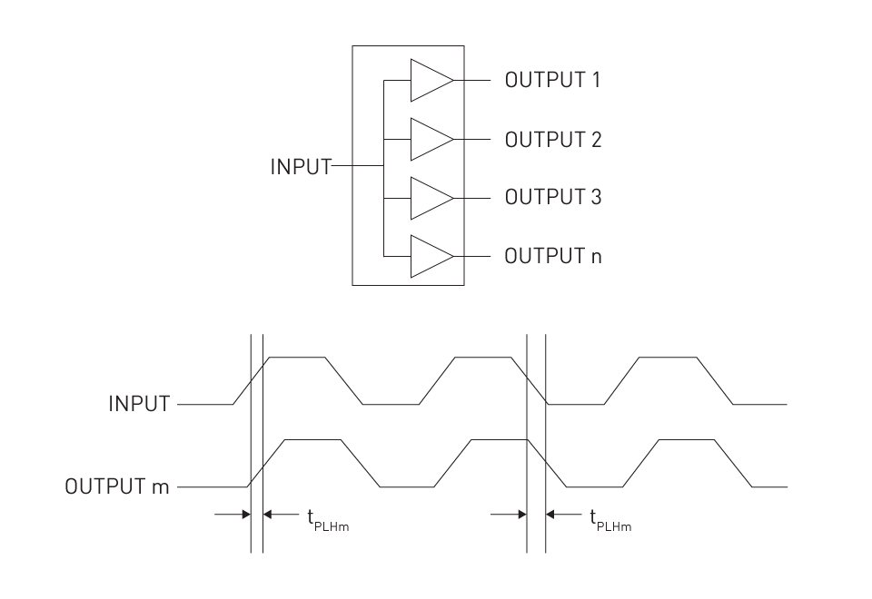
Figure 1: Pulse Skew
Synchronization Challenges: Applications necessitating precise timing synchronization, like high-speed data communication or digital signal processing, may encounter data errors and system malfunctions due to pulse skew. In parallel data transfer, where the simultaneous arrival of all bits is anticipated, this issue becomes particularly problematic.
Signal Integrity Degradation: The integrity of the signal can be degraded by the inaccurate pulse timing due to skew. In digital systems, where accurate data interpretation relies on the precise timing of signal edges, this degradation proves especially detrimental.
Increased Bit Error Rates: Communication systems may experience heightened bit error rates due to significant pulse skew, which in turn impacts the dependability and efficiency of data transmission.
Minimizing Pulse Skew
Careful Channel Design: To significantly diminish pulse skew, one must optimize the internal design of the digital isolator. This entails ensuring uniform propagation delays across all channels through the implementation of a symmetrical layout and maintaining consistent electrical attributes for each channel.
Material and Fabrication Consistency: Achieving more uniform channel characteristics and reducing pulse skew can be facilitated by employing high-quality materials and upholding consistency in fabrication processes.
Skew Compensation Techniques: The effects of pulse skew can be alleviated by incorporating skew compensation tactics in the system design. Incorporating delay elements into faster channels or utilizing advanced signal processing algorithms are potential approaches to address this matter.
Temperature and Voltage Stability: To mitigate pulse skew, it's essential to uphold stable operating conditions, including consistent supply voltage and temperature, which can aid in minimizing variations in propagation delay across channels.
Selection of Suitable Isolators: It is important to select digital isolators with low inherent pulse skew as per their specifications. Designers are enabled to choose isolators that fulfill the timing needs of their application, as manufacturers commonly specify the maximum pulse skew.
System-Level Testing and Calibration: At the system level, conducting thorough testing and calibration can recognize and compensate for pulse skew. This guarantees reliable performance of the overall system, even if a certain level of skew is present in the isolators.
Isolation Barrier Life
In digital isolators, the determination of longevity and reliability across various applications hinges on the critical specification of isolation barrier life. To guarantee safety and sustained performance over the device’s lifespan, isolation barrier life plays a crucial role.
Definition and Importance: The time period over which the isolation barrier within a digital isolator can effectively avert electrical conductivity and uphold signal integrity is known as isolation barrier life. In applications where isolators endure continual electrical stress, this becomes crucial. Over time, the degradation of the isolation barrier can fail to maintain sufficient electrical isolation, thereby posing risks to both user safety and system functionality. For instance, modern digital isolators have a typical isolation barrier life of more than 25 years.
Factors Influencing Barrier Life
Material Properties: The lifespan of the isolation barrier is significantly influenced by the materials used in its construction, including the dielectric in capacitive isolators or the core material in magnetic isolators. A longer barrier life is offered by materials that are more resistant to environmental factors and electrical stress.
Electrical Stress: The longevity of the isolation barrier is impacted by the level of voltage and current stress it regularly faces. Accelerated degradation can occur with frequent exposure to high-voltage transients or continuous operation at high voltages.
Environmental Conditions: Over time, the integrity of the isolation barrier can be affected by external elements such as humidity, temperature fluctuations, and exposure to corrosive atmospheres.
Quality of Manufacturing: To guarantee a strong and long-lasting isolation barrier, the accuracy and quality of the manufacturing process, like the adherence to stringent production standards and the cleanliness of the fabrication environment play a pivotal role.
Assessing Barrier Life
Standardized Testing: Through standardized tests that simulate expanded operating conditions, manufacturers typically evaluate the isolation barrier life. Accelerated aging processes and stress testing under numerous electrical and environmental conditions are included in these tests.
Specified Ratings: In the product documentation, the expected barrier life is frequently specified, offering designers an approximation of the isolator's lifespan under normal operating conditions.
Impact on System Design
Safety Margins: While choosing isolators, especially for crucial applications, designers must consider the isolation barrier life. To provide additional safety margins, selecting isolators with a barrier life surpassing the expected lifespan of the product is advisable.
Maintenance and Replacement Schedules: In planning maintenance and replacement schedules for systems employing digital isolators, comprehending the barrier life is crucial. This ensures uninterrupted operation, free from unexpected failures.
Operating Temperature Range
The fundamental specification of digital isolators lies in their operating temperature range, depicting the environmental conditions conducive to their reliable functionality. For applications exposed to extreme or fluctuating temperatures, this specification is important.
Definition and Relevance: Specifying both the minimum and maximum ambient temperatures, the operating temperature range outlines the conditions under which a digital isolator can function reliably without experiencing performance degradation. In applications characterized by prevalent temperature variations, such as industrial, automotive, or outdoor settings, this range assumes crucial importance. Typically, modern digital isolators operate within a temperature range of -40°C to +125°C. However, isolators engineered for greater operating temperatures boast broader ranges, reaching up to -55°C to +175°C.
Factors Influencing Temperature Range
Material Properties: How a digital isolator withstands temperature extremes is determined by the materials utilized in its construction, encompassing isolation barriers and semiconductor components.
Circuit Design: The isolator's capability to dissipate heat and operate in various temperatures is influenced by the design of its internal circuitry, encompassing factors such as component density and layout.
Packaging Technology: The role of thermal management and resistance to temperature variations is significant in the packaging material and technology utilized to encase the digital isolator.
Impact on System Performance
Signal Integrity: Extreme temperatures can induce changes in the electrical properties of the components within the isolator, potentially impacting signal integrity and timing.
Longevity and Reliability: Acceleration of aging and wear-out mechanisms, leading to reduced lifespan and reliability of the isolator, can occur when operating outside the specified temperature range.
Safety Considerations: Device failure, which could pose safety risks in critical applications, may result from exceeding the temperature limits.
Optimizing for Temperature Range
Material Selection: For superior performance across a broader temperature range, it is necessary to opt for materials with higher thermal stability for both the semiconductor components and the isolation barrier.
Thermal Design Considerations: To maintain optimal operating temperatures, effective thermal management strategies, including heat sinks, thermal vias, and sufficient spacing for air circulation, can be implemented.
Robust Testing: To ensure that the isolator meets its specified operating range, rigorous testing under varying temperature conditions is essential. Both low-temperature and high-temperature endurance testing are included in this.
Application-Specific Selection
Industrial and Automotive Applications: Devices with a wide and robust temperature range are often required in these sectors, where digital isolators must frequently operate in extreme and rapidly changing temperatures.
Consumer Electronics: The required temperature range in typical home or office environments might be narrower, thus permitting more standard design strategies and material choices.
Size
In modern electronic systems, where space constraints are prevalent, the size of digital isolators emerges as a critical specification deserving particular attention. System design and integration are profoundly influenced by the physical dimensions of these components.
Importance of Compact : The demand for smaller elements, like digital isolators has been elevated as electronic devices become increasingly miniaturized. Applications such as portable devices, wearables, and space-constrained industrial controls frequently determine the suitability of isolators based on their size.
Factors Influencing Size
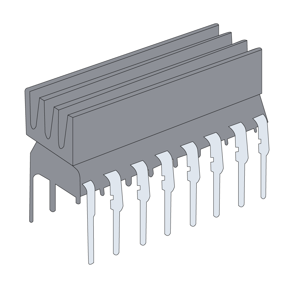
Isolation Technology: The size of the isolator is inherently influenced by the method of isolation employed, whether it be capacitive, magnetic, or optical. Capacitive isolators, for instance, can be crafted to be smaller compared to magnetic ones, due to the absence of heavy structures of transformer.
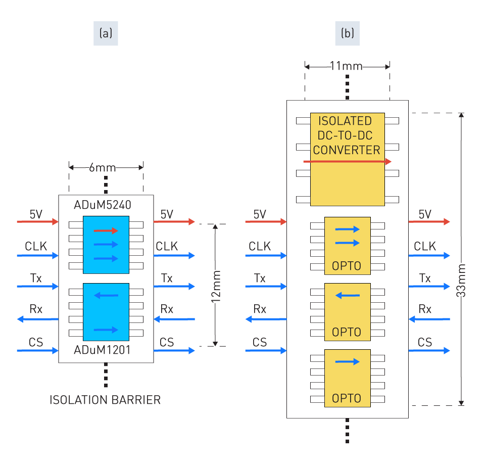
Figure 2: Isolators Based on (a) Magnetic Isolation and (b) Optocouplers
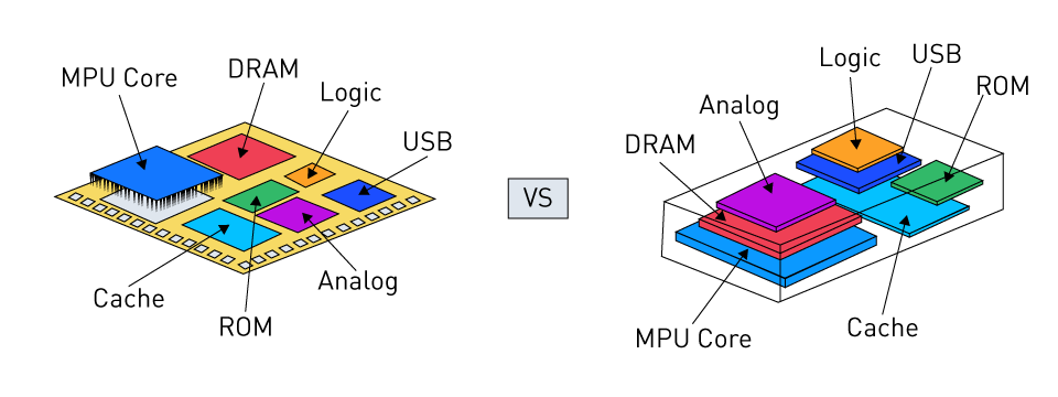
Integration Level: Incorporating multiple functions into a single chip, as seen in system-on-chip (SoC) designs, can drastically diminish the size of the isolator, thereby influencing the degree of integration.
Packaging Techniques: More compact isolators, without compromising performance, are made possible by advances in packaging technology, such as chip-scale packaging (CSP) and multi-chip modules (MCMs).
Impact on System Design
Board Space Optimization: Allowing for more efficient utilization of printed circuit board (PCB) space, smaller digital isolators facilitate denser and more intricate circuit designs.
Flexibility in Placement: Greater flexibility in placement within a system is facilitated by compact isolators, enhancing layout and routing options, ultimately leading to potential improvements in thermal management and signal integrity.
Portability and Form Factor: The overall form factor and portability of products in consumer electronics and portable devices are directly impacted by the size of the components.
Design Considerations
Balancing Size and Performance: Desirable for space-saving purposes, smaller isolators necessitate a careful balance between size reduction and meeting performance requirements. This ensures that the isolator maintains the required electrical parameters.
Thermal Management: Managing heat dissipation becomes more complicated as isolators become smaller. To prevent overheating, which could impact reliability and lifespan, designers must take thermal aspects into consideration.
Manufacturability: Challenges in manufacturing and assembly processes, like elevated complexity in placement and soldering on PCBs can be posed by extremely small parameters.
Channel Configurations
In system design, the choice between single and multi-channel isolators significantly influences performance and application suitability, thereby playing a crucial role in digital isolators' channel configurations.
Single- and Multi-Channel Isolators
Single-Channel Isolators
- Design: Consisting of a single isolation path between the input and output, single-channel isolators find typical applications in scenarios where only one signal necessitates isolation.
- Applications: Commonly found in applications such as isolated power supply feedback, sensor interfaces, and signal conditioning circuits, single-channel isolators are well-suited for simpler systems or situations where isolation needs are confined to a single data line or control signal.
Multi-Channel Isolators
- Design: Various independent isolation channels in a single package are provided by the multi-channel isolators. Devices may offer a varying number of channels, with some providing up to six or more channels.
- Applications: Frequently employed in data acquisition systems, industrial automation, and communication interfaces, multi-channel isolators are well-suited for more complex systems where multiple signals necessitate isolation simultaneously.
Configuration Impact on Performance and Application
System Complexity and Integration
- Single-Channel Isolator: While these isolators offer simplicity and potential for compactness, employing numerous single-channel isolators within a system may elevate both complexity and board space requirements.
- Multi-Channel Isolator: By consolidating several isolation channels into a single package, multi-channel isolators have the capability to decrease system complexity, thus preserving board space and streamlining design.
Cost Implications
- Single-Channel Isolator: For applications necessitating only one or two isolated channels, single-channel isolators may offer a more cost-effective solution.
- Multi-Channel Isolator: When multiple isolation channels are required, multi-channel isolators generally offer a more cost-efficient solution by reducing the total component count.
Performance Considerations
- Single-Channel Isolator: Single-channel isolators, featuring fewer internal components, may occasionally provide superior performance in terms of data rate and lower power consumption.
- Multi-Channel Isolator: Incorporating integration advantages, multi-channel isolators may exhibit slightly reduced performance per channel attributable to internal crosstalk and thermal considerations. Yet, ongoing advances in design and technology consistently work towards alleviating these concerns.
Flexibility and Redundancy
- Single-Channel Isolator: Each isolator can be individually placed and utilized, allowing for greater flexibility in system design.
- Multi-Channel Isolator: In systems where reliability is critical, the provision of redundancy within a single package can be advantageous.
Thermal Management
- Single-Channel Isolator: Due to fewer internal components in single-channel isolators, it is typically easier to manage heat dissipation.
- Multi-Channel Isolator: Due to the greater density of components and resultant heat generation, more careful thermal management is required by multi-channel isolators.
Isolation Voltage and Common-Mode Transient Immunity (CMTI)
Ensuring the safety and integrity of electronic systems employing digital isolators crucially hinges on understanding isolation voltage and CMTI.
Importance in System Safety and Integrity
Isolation Voltage
- Definition: The maximum voltage that can be applied across the isolator’s input and output without breakdown is known as isolation voltage. Ensuring safety and long-term reliability is imperative for both the isolator and the system it safeguards, making this parameter indispensable.
- Safety Implications: In high-voltage applications such as power supply units and industrial control systems, adequate isolation voltage is vital to safeguard against electric shocks and ensure user safety.
- System Integrity: By preventing electrical surges or faults from propagating through the system, a robust isolation voltage level helps maintain system integrity, thereby averting potential damage or malfunction of sensitive components.
Common-Mode Transient Immunity (CMTI)
- Definition: Measured typically in kilovolts per microsecond (kV/μs), CMTI quantifies the isolator’s capacity to endure rapid changes in the potential difference between two grounds, known as common mode, without inducing errors. In electrically noisy environments, CMTI is considered as a key indicator.
- Signal Integrity: Typical in industrial and automotive environments, common mode transients are effectively managed by high CMTI, ensuring the maintenance of signal integrity by the digital isolator.
- Reliability: Contributing to overall functional stability and longevity, systems with high CMTI ratings are more reliable in the face of electrical noise.
Optimal Selection Based on Application Needs
Selection Criteria for Isolation Voltage
- Application-Specific Voltage Requirements: In selecting isolation voltage, it's essential to match it with the voltage levels pertinent to the application. For instance, isolators with higher isolation voltage ratings may be necessary for industrial applications, contrasting with the requirements of consumer electronics.
- Regulatory and Safety Standards: The minimum isolation voltage requirements for a particular application are frequently determined by compliance with relevant safety standards, such as those set by UL and IEC.
Selection Criteria for CMTI
- Environmental Noise Levels: The choice of digital isolators with high CMTI ratings is paramount in environments characterized by high electrical noise, such as those found in motor drives or power converters.
- Performance Under Transient Conditions: Isolators with superior CMTI capabilities are preferable for applications sensitive to transients or where signal integrity is of utmost importance.


直接登录
创建新帐号