Brushed vs. Brushless DC motors
In the motor industry, the two primary varieties are brushless and brushed DC motors. Various types suit a variety of applications due to their unique working principles, construction, advantages, and limitations.
Brushed DC Motors
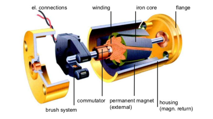
Working Principles: Electromagnetic induction is the underlying concept that drives brushed DC motors' operation. The commutator, a rotating electrical switch, contacts carbon brushes that apply current to the motor's armature, the rotating component. Current flows through the armature windings, creating a magnetic field. Permanent magnets or field windings produce a stationary field that interacts with this magnetic field. This interaction generates torque, which in turn causes the armature to roll.
Construction and Components: The rotor coils, stator permanent magnets, brushes, and commutator are the key components that make up a brushed DC motor at the construction level. The commutator and brushes are responsible for facilitating the electrical connection to the rotor coils. This connection ensures that the rotor will rotate continuously by occasionally reversing the direction of the current in the windings. The rotor coils in a conventional direct-current (DC) motor wind around an iron core inside the motor.
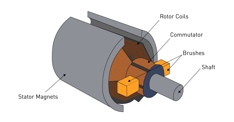
Figure 3: Components Of The Traditional Brushed DC Motor
The motor may also be of the coreless variety, in which the rotor is constructed from windings that form a self-supporting, hollow cylinder and are held together with epoxy. This type of motor does not have an iron core for its rotor. The motor housing attaches the stator, which completes the electrical circuit. The stator's permanent magnets are housed inside the rotor. Bearings hold the rotor in place as it rotates around the stator.
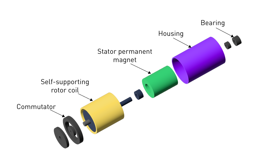
Figure 4: Coreless Brushed DC Motor
Advantages and Limitations: There are a number of benefits and drawbacks to brushed DC motors. Some of the advantages include simplicity, low initial cost, and ease of control. Their dependability is exceptional in settings where there is a concern for electronic noise. When compared to brushless motors, their efficiency is lower, and their lifespan is shorter due to the mechanical wear and tear that occurs on the brushes and commutator. However, their drawbacks include the need for maintenance due to the brushes' wear.
Brushless DC Motors
Working Principles: By positioning the permanent magnets on the rotor and the windings on the stator, brushless DC (BLDC) motors are able to operate in a manner that is perverse to the architecture of brushed motors. Electronic controllers, replacing mechanical brushes and commutators, switch the current in the stator windings to form a revolving magnetic field that powers the rotor. This electronic commutation allows for precise control over the motor's operation.
Construction and Components: A BLDC motor consists of a rotor with permanent magnets, stator windings, and an electronic controller with sensors to detect the rotor's position. The controller uses this information to determine the appropriate timing for switching current in the stator windings, resulting in the generation of a magnetic field that rotates the rotor.
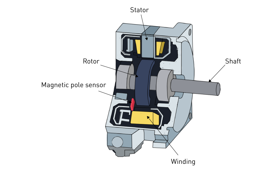
Figure 5: BLDC (Brushless DC) Motor
Advantages and Limitations: The primary benefits of brushless direct current (BLDC) motors are their high efficiency, reliability, and extended lifespan due to the elimination of brushes. However, there are also disadvantages. In addition to having low noise levels and a compact size, they have favorable speed-to-torque characteristics. A higher initial cost and the complexity of the electronic control systems that are necessary for their operation are two of their limitations
Brushed vs. Brushless DC Motors: A Comparison
When choosing between brushless and brushed direct current (DC) motors, one must take into account a number of factors, including cost, performance requirements, maintenance capabilities, and the specific demands of the application. Applications that demand high efficiency, reliability, and minimal maintenance tend to favor brushless motors. Brush electric motors, on the other hand, are advantageous due to their simplicity and inexpensive cost. The table on the following page provides a comparison of the most important parameters.
Table 1: Comparison of Brushed and Brushless DC Motors
| Brushed Motor | Brushless Motor | |
| Lifetime | Short (brushes wear out) | Long (no brushes to wear) |
| Speed and Acceleration | Medium | High |
| Efficiency | Medium | High |
| Electrical Noise | Noise (bush arcing) | Quiet |
| Acoustic Noise & Torque Ripple | Poor | Medium (trapezoidal) or good (sine) |
| Cost | Lowest | Medium (added electronics) |
Permanent Magnet Stators vs. Wound Stators
The distinction between Wound Stators and Permanent Magnet Stators is significant.
When it comes to DC motors, the decision between permanent magnet stators and winding stators has a considerable impact on the performance, purpose, and design of the motors. Regarding the motor's efficiency, cost, and control characteristics, this differentiation is of the utmost importance.
DC Motors with Permanent Magnet Stators
For the purpose of producing the magnetic field against which the armature interacts, permanent magnet DC (PMDC) motors make use of permanent magnets. This design simplifies the motor structure by eliminating the need for field windings and the power supply that usually goes with them
Working Principles: Permanent magnets produce a magnetic field that the rotor, also known as the armature, places within to operate PMDC motors. The magnetic field of the stator generates a magnetic force that is perpendicular to the flow of current when current is flowing through the windings of the rotor. This phenomenon causes the rotor to experience torque.
Advantages and Limitations: PMDC motors have a number of advantages, the most significant of which is their relative ease of use and great efficiency. This is because they do not require any power to generate an external magnetic field. Temperature and age can also alter the magnetic strength of the permanent magnets, preventing them from producing a torque output beyond their capabilities. These permanent magnet direct current (PMDC) motors are often more expensive than their wrapped stator counterparts. This is because high-quality magnets in the stator, such as neodymium, are more expensive.
DC Motors with Wound Stators
DC motors with wound stators use windings to successfully generate the magnetic field. These motors fall into three categories: series, shunt, and compound. By altering the field winding connections, each of these motors offers a distinct set of properties.
Series DC Motors:
DC motors in series are characterized by the fact that they connect the field windings in series with the armature. Series motors are appropriate for applications that require powerful initial movement such as electric vehicles and cranes, because this arrangement enables the motor to deliver a large starting torque despite its relatively modest starting torque.
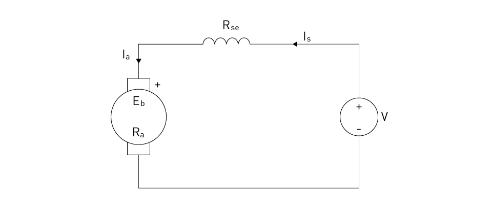
Figure 6: Substitution circuit of The Series DC Motor
The equation that governs behavior after reaching a steady state is as follows:
$$V=Ia (Ra+Rse)+Eb$$Where:
V represents the applied voltage to the motor terminals.
Ia represents the armature current.
Ra represents the armature circuit resistance (including brushes and contacts).
Rse represents the resistance of the armature winding.
Eb represents the back EMF (Electromotive Force) generated in the armature due to rotation.
Shunt DC Motors:
Shunt motors, also known as parallel motors, are characterized by the fact that they connect the field windings in parallel with the armature. For applications that require precision control, such as conveyor belts and lathe machines, this design provides good speed regulation and a speed that remains relatively constant under variable loads.
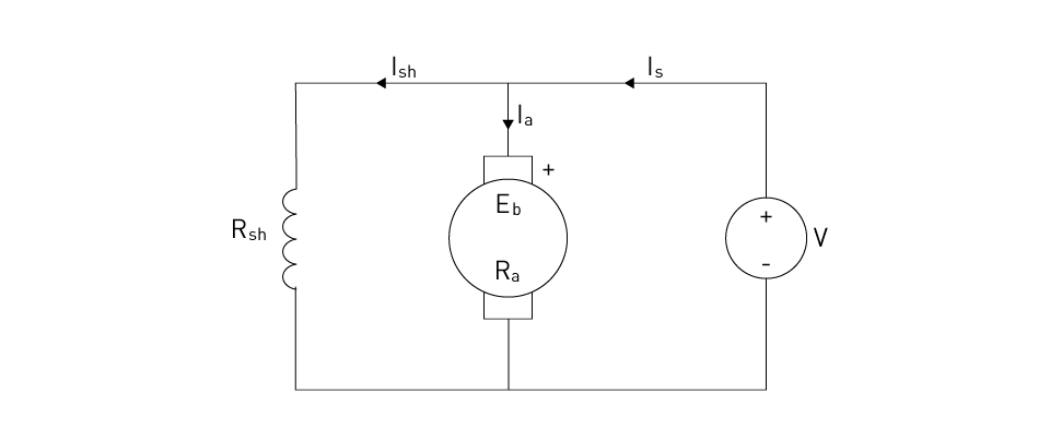
Figure 7: Substitution circuit of The Shunt DC Motor
The equation that governs behavior after reaching a steady state is as follows:
$$V=Ia \times Ra+Eb$$Where:
V represents the applied voltage to the motor terminals.
Ia represents the armature current.
Ra represents the armature circuit resistance (including brushes and contacts).
Eb represents the back EMF (Electromotive Force) generated in the armature due to rotation.
Compound DC Motors:
Compound motors contain both series and shunt winding designs, providing a balance between high beginning torque (a characteristic of series motors) and effective speed regulation (a characteristic of shunt motors). A wide variety of applications, ranging from heavy-duty industrial gear to automotive starters, can benefit from their versatility as a result of this.
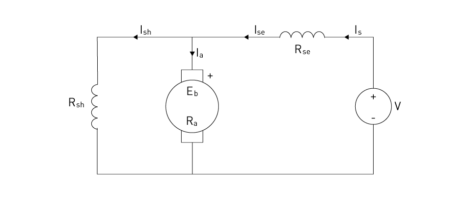
Figure 8: Substitution circuit of The Compound DC Motor
The equation that governs behavior after reaching a steady state is as follows:
$$V=Ise \times Rse+Ia \times Ra+Eb$$Where:
V represents the applied voltage to the motor terminals.
Ise represents the series field current
Ia represents the armature current.
Rse represents the resistance of the armature winding.
Ra represents the armature circuit resistance (including brushes and contacts).
Eb represents the back EMF (Electromotive Force) created in the armature due to rotation.
Advantages and Limitations:
It is possible to design wound stator DC motors to meet the requirements of a particular application by adjusting the winding configuration. However, this versatility comes with some limitations. These motors offer more robust torque characteristics and are generally more affordable than PMDC motors. On the other hand, they consume more power in the field windings, making them less efficient and necessitating more winding maintenance.
Self-excited vs. Separately Excited DC Motors
Direct current (DC) motors fall into two categories: self-excited and separately excited, due to the source of the magnetic field necessary for their functioning. This differential impacts performance, control qualities, and applicability for a variety of applications.
Self-excited DC Motors
The built-in windings of self-excited direct current (DC) motors generate their magnetic field. As previously mentioned, the field winding connections distinguish three basic categories of self-excited motors: shunt, series, and compound configurations. Either the same power source as the armature or the armature itself directly energizes the field windings of these motors.
Advantages and Limitations: People frequently use self-excited motors due to their ease of use and versatility. However, they also have some limitations. For instance, changes in supply voltage and, in the case of series motors, the load that is applied to the motor can both have an effect on the performance of these motors. Care and maintenance of the windings and brushes (in the case of brushed versions) is another factor to keep in mind.
Separately Excited DC Motors
An external power source energizes the field windings of differentiated alternating current (DC) motors, independent of the armature circuit. This allows for more precise control of the motor's magnetic field and, consequently, its performance characteristics.
Working Principle: The working principle of independently excited motors allows for precise regulation of the magnetic field intensity without altering the armature current. Consequently, this allows for highly precise control of the motor's speed and torque output.
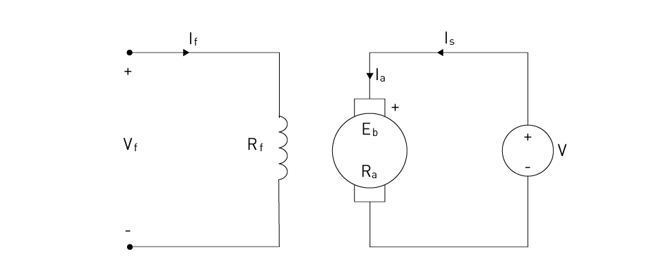
Figure 9: Substitution Circuit of the Separately Excited DC Motor
The ruling equation of steady state behavior as follows:
$$V=Ra \times Ia+Eb=Ra \times Ia+Laf \times If \times w$$Where:
V represents the applied voltage to the armature terminals.
Ia represents the armature current.
Ra represents the armature circuit resistance (including brushes and contacts).
Eb represents the back EMF (Electromotive Force) generated in the armature due to rotation.
Laf represents the mutual inductance between the armature and field windings.
If represents the field current.
w represents the motor speed.
Advantages and Limitations: The primary benefit of individually excited DC motors is that they offer superior control over speed and torque. This makes them a perfect choice for applications that require accuracy, such as robotics and process control systems. However, there are also some limitations associated with these designs. The need for a separate power source for the field windings complicates and increases the cost of the motor control system.
Comparison and Applications: Choosing between self-excited and separately excited DC motors is contingent upon the particular requirements of the application. These requirements encompass the required level of control, desired performance characteristics, and cost constraints. Motors that are self-excited offer a solution that is simpler and more cost-effective for a wide variety of applications, whereas motors that are separately excited give superior control at the sacrifice of complexity and cost. It is essential to have a thorough understanding of the distinctions that exist between these different types of DC motors in order to carefully select the motor type that is most suitable for each given application, taking into account both the performance requirements and the economic factors involved.




直接登录
创建新帐号